|
No hay comentarios de productos.
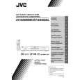
XV-SA600BK/XV-SA602SL 2.2 Loading assembly section 2.2.1 Removing the clamper assembly (See Fig.2-8) (1) Remove the four screws A attaching the clamper assembly. (2) Move the clamper in the direction of the arrow to release the two joints a on both sides. ATTENTION: When reattaching, fit the clamper to the two joints a.
Joint a
Joint a
A
A
Clamper assembly
A
A
Fig.2-8 2.2.2 Removing the tray (See Fig2-9. and 2-10) � Prior to performing the following procedure, remove the clamper assembly. (1) Push b of the slide cam into the slot on the left side of the loading base until it stops. (2) Draw out the tray toward the front. ATTENTION: Before reattaching the tray, slide the part c of the slide cam to the right as shown in Fig.2-10.
Loading base Push b Fig.2-9 Tray
Part c
Slide cam Fig.2-10
9
|