|
No hay comentarios de productos.
In such
a case,
check
rdso if the POWER
AMPLIFIER
circuit
or power
supply
circuit
has any
abnormalities
or not.
2-2.
Regarding
There power When
reset
that the machine does not work reset occurs, In such correctly (pressing because the STOP to wrong the MICROCOMPUTER key + POWER key) is not reset is performed. is defective and check good and to or no even though the AC
are cases cord
is re-inserted, described
or the software phenomenon
the above
it can leads perform
judgment
as if the MICROCOMPUTER by the following procedure
exchange good @)
the MICROCOMPUTER.
a case,
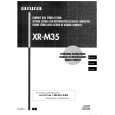
the forced-reset
of the MICROCOMPUTER. Remove the AC power cord.
FRONT
C.B
~@vss
*�
15~\
MICRO�-�TTJTER
\
FRONT
o
C.B d
Short
with
tweezers.
Fig-2-2
@ @
Short Connect
the both
ends
of the electrolytic cord again.
capacitor
Cl 13 that
is connected returns
to VDD
of the MICROCOMPUTER operation,
with
tweezers.
the AC power
If the MICROCOMPUTER
to the normal
the MICROCOMPUTER
is good.
Note:
The reference depending
number
or MICROCOMPUTER Be sure to check
pin number the reference
of transistor numbers
(Ql
10) and electrolytic diagram before
capacitor starting
(Cl 13) can change the discharging work.
on the models.
on schematic
2-3.
Confirmation
Check
of soldering
state after
state
of MICROCOMPUTER
in addition the trouble to the above described procedures. Be sure to exchange the
the soldering
of the MICROCOMPUTER surely confirming that
MICROCOMPUTER itself.
is not caused
by poor
soldering
but the MICROCOMPUTER
TRANSISTOR
ILLUSTRATION
ECB
ffhiibf
ECB
B
BCE
2SA933S 2SC5395
2SA952 2SC1815 2SD655 C2N5551 CSBI CSD655 CSD1489 KTAI 266 058
2SAI
235
DTCI DTCI
14TK 44EK
2SB1481 2SD2241
2SK2158
2SC2714 2SC3052 CMBT5401 CMBT5551 DTA143EK DTA144TK
KTA1 298 RT1 N144C RT1 P141C RTI RTI P144C P441 C
KTC3198
6
|