|
|
|
Productos
|
|
Información
|
|
Destacado
|
|
|
 |
|
|
No hay comentarios de productos.
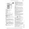
XR-CA330/CA340
Connection diagram
Supplied with the XA-C30
Supplied with the CD/MD changer
Source selector (not supplied)
BUS AUDIO IN BUS CONTROL IN
from a car aerial
BUS AUDIO IN
AUDIO OUT
AUDIO OUT
RCA pin cord (not supplied) Fuse (10 A)
7
AMP REM
Blue/white striped White White/black striped Left
Max. supply current 0.3 A to AMP REMOTE IN of the optional power amplifier This connection is only for ampilifiers. Connecting any other system may damage the unit.
XR-CA340 only
to the interface cable of a car telephone
ATT
Sky blue
Grey Right Grey/black striped
to the power aerial control lead or power supply lead of aerial booster amplifier Notes � It is not necessary to connect this lead if there is no power aerial or aeria booster, or with a manually-operated telescopic aerial. � When your car has a built-in FM/AM aerial in the rear/side glass, see �Notes on the control and power supply leads.�
Green Left
ANT REM
Max. supply current 0.1 A
Blue
Green/black striped
Purple Right Purple/black striped
Yellow
to the +12 V power terminal which is energized at all times Be sure to connect the black earth lead first.
to the +12 V power terminal which is energized at the accessory position of the ignition key switch Notes � If there is no accessory position, connect to the +12 V power (battery) terminal which is energized at all times. Be sure to connect the black earth lead to it first. � When your car has a built-in FM/AM aerial in the rear/side glass, see �Notes on the control and power supply leads.�
Red
Black
to a metal place in the car First connect the black earth lead, then connect the yellow and red power input leads.
Notes on the control and power supply leads � The power aerial control lead (blue) supplies +12 V DC when you turn on the unit. � When your car has a built-in FM/AM aerial in the rear/side glass, it is necessary to connect the power aerial control lead (blue) or the accessory power input lead (red) to the power terminal of the existing aerial booster. For details, consult your dealer. � A power aerial without a relay box cannot be used with this unit. Memory hold connection When the yellow power input lead is connected, power will always be supplied to the memory circuit even when the ignition switch is turned off. Notes on speaker connection � Before connecting the speakers, turn the unit off. � Use speakers with an impedance of 4 to 8 ohms, and with adequate power handling capacities. Otherwise, the speakers may be damaged. � Do not connect the terminals of the speaker system to the car chassis, and do not connect the terminals of the right speaker with those of the left speaker. � Do not attempt to connect the speakers in parallel. � Do not connect any active speakers (with built-in amplifiers) to the speaker terminals of the unit. Doing so may damage the active speakers. Be sure to connect passive speakers to these terminals.
6
|
|
|
> |
|