- GENERAL
- Location of Controls
- Setting the Clock
- Labelling the Rotary Commander
- Using the Rotary Commander
- Installation
- Connection
- DISASSEMBLY
- ASSEMBLY OF MECHANISM DECK
- MECHANICAL ADJUSTMENTS
- ELECTRICAL ADJUSTMENTS
- Test Mode
- Tape Deck Section
- Tuner Section
- DIAGRAMS
- Printed Wiring Boards - Main Section - (Side A)
- Printed Wiring Boards - Main Section - (Side B)
- Schematic Diagram - Main (1/2) Section
- Schematic Diagram - Main (2/2) Section
- Printed Wiring Board - Panel Section (Side A), (Side B)
- Schematic Diagram - Panel Section
- IC Pin Function Description
- EXPLODED VIEWS
- ELECTRICAL PARTS LIST
No hay comentarios de productos.
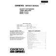
SECTION 3 ASSEMBLY OF MECHANISM DECK
Note: Follow the assembly procedure in the numerical order given.
HOUSING
5 Fit projection on C part. 2 Install the hanger onto two claws of the housing. 4 Fit claw on B part.
7 Holder the hanger by bending the claw. 1 Install the catch to the hanger.
hanger
3 Put the housing under A part.
6 Fit projection on D part.
housing
C part 8 Hold the hanger by bending the claw.
D part
A part
B part
ARM (SUCTION)
2 Move the arm (suction) in the arrow direction and fit on projection.
projection
1 Fit the arm (suction) on the shaft.
� 10 �
|