Su carrito de compras está vacío
 
English Polski Spanish 
Buscar un manual
 

(p.Ej. AA-V20EG JVC, ZX-7 Sony)
PayPal 1000+ rating Secure, Encrypted Checkout.
 
Usuarios conectados
Actualmente hay 6043 visitantes online.
Productos
Información
Destacado
Inicio >> JVC >> XMPX5SL Manual de Servicio
 
 0 artículo(s) en Su carrito 

JVC XMPX5SL
Manual de Servicio


¡Twitee acerca de este producto y obtenga $1.00 de crédito en la tienda para uso!
  • Contiene diagramas del circuito
  • Descargable
  • Formato PDF
  • Manual completo
  • Idiomas: English
Precio: $4.99

Descripción del JVC XMPX5SL Manual de Servicio

Manual de servicio completo en formato digital (archivo PDF). Los manuales de servicio por lo general contienen diagramas de circuitos, tarjetas de circuitos impresos, consejos para reparación, diagramas de cableado, diagramas de bloque y lista de refacciones. El Manual de Servicio (a veces llamado Manual de Reparación) es usado principalmente por los técnicos.

Si tan solo quiere saber cómo utilizar su televisión, reproductor de vídeo, reproductor de mp3, etc. Quizá lo que necesita es el Manual del Propietario. Después de colocar la orden le enviaremos las instrucciones de descarga a su dirección de e-mail.

The manual is available in languages:

Añadir al carro:

Not yet ready
You must purchase it first

Opiniones de los clientes
No hay comentarios de productos.

TEXT_PDF_SNIPPET
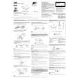
XM-PX5SL Removing the chassis ass�y (See Fig.5 and 6)
1. Remove the two screws B and the one screw C attaching the chassis assy. Remove the one screw D attaching the jack cover. 2. Open the battery lid and release the tab d from the battery contact. Pull out the battery lid. 3. Remove the one screw E attaching the arm (L). 4. Remove the chassis ass�y and the arm (L) while releasing them from the headphone jack on the bottom case.
Battery lid

B

Chassis ass'y

B

Bottom case

D C

Headphone jack Jack cover

Removing the main P.W. board and the battery holder(See Fig.7 and 8)
1. Use a soldering bit provided with ground to solder or unsolder the short round.

Fig.5

Headphone jack

2. Ground the set and the P.W.board. The voltage level of the ground should be equal to that of the soldering bit. 3. Prevent static electricity using an earth band, etc. 4. Solder the short round of the pickup FRC for short circuit. 5. Disconnect the flexible wires from the connector CN301 and CN801 on the main P.W.Board.

d Arm (L)

E
6. Remove the one screw F attaching the main P.W.board. Remove the main P.W.board and the battery holder, then reverse them. 7. Disconnect the flexible wire from connector CN601 on the main P.W.board.
Battery holder Soldering

Fig.6

8. Unsolder the soldered joint of the main P.W.board and the battery holder P.W.board.
Battery holder MD mechanism ass'y

F
CN401

Pickup short round CN601 Main P.W.board

CN301 Main P.W.board

Fig.8

Fig.7

1-6

Quizás también quiera comprar

$4.99

XMPX5SL JVC
Diagrama del circuito

Conjunto de diagramas del circuito. Los diagramas serán proporcionados en un archivo PDF. El archiv…

$4.99

XMPX5SL JVC
Manual de Usuario

Manual del propietario completo en formato digital. El manual estará disponible para descarga como …
>
Parse Time: 0.161 - Number of Queries: 104 - Query Time: 0.036