Su carrito de compras está vacío
 
English Polski Spanish 
Buscar un manual
 

(p.Ej. AA-V20EG JVC, ZX-7 Sony)
PayPal 1000+ rating Secure, Encrypted Checkout.
 
Usuarios conectados
Actualmente hay 5769 visitantes online.
Productos
Información
Destacado
Inicio >> AIWA >> WDX500 Manual de Servicio
 
 0 artículo(s) en Su carrito 

AIWA WDX500
Manual de Servicio


¡Twitee acerca de este producto y obtenga $1.00 de crédito en la tienda para uso!
  • Contiene diagramas del circuito
  • Descargable
  • Formato PDF
  • Manual completo
  • Idiomas: English
Precio: $4.99

Descripción del AIWA WDX500 Manual de Servicio

Manual de servicio completo en formato digital (archivo PDF). Los manuales de servicio por lo general contienen diagramas de circuitos, tarjetas de circuitos impresos, consejos para reparación, diagramas de cableado, diagramas de bloque y lista de refacciones. El Manual de Servicio (a veces llamado Manual de Reparación) es usado principalmente por los técnicos.

Si tan solo quiere saber cómo utilizar su televisión, reproductor de vídeo, reproductor de mp3, etc. Quizá lo que necesita es el Manual del Propietario. Después de colocar la orden le enviaremos las instrucciones de descarga a su dirección de e-mail.

The manual is available in languages: English

Not yet ready
You must purchase it first

Opiniones de los clientes
No hay comentarios de productos.

TEXT_PDF_SNIPPET
CAUTIONS WHEN SERVICING
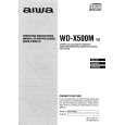
1. Disassembly Procedure 1) Remove the COVER BOTTOM. 2) Remove the screws (pointed by the arrows), and then remove the DECK MECHANISM. See Fig. 1.

Fig-1

3) Remove the COVER TOP. 4) Remove the screws (pointed by the arrows), and then remove the CD MECHANISM. See Fig. 2.

2. Service Position Check the operation in the stable status (using a plate, etc.). See Fig. 3.
Fig-2

Fig-3

3. Test Mode 1. Starting CD Test 1) Use solder to short-circuit the TEST lands. See Fig. 4. 2) Connect the ACC/BACKUP wire of connector assembly to the positive (+) terminal of power supply unit, and the ground wire, to the negative (-) terminal. 3) Adjust the voltage of power supply unit to 14.5 V, and then turn the power on. The test mode will start, and all LCD segments will light. See Fig. 5.

IC401

SOLDER BRIDGE

IC901

Fig-4

2. Releasing CD Test Mode 1) Turn the power supply unit off. 2) Disconnect each wire of connector assembly. 3) Remove the solder from the TEST lands on the Main C.B.
Fig-5

-4-

Quizás también quiera comprar

$4.99

WDX500 AIWA
Manual de Usuario

Manual del propietario completo en formato digital. El manual estará disponible para descarga como …
>
Parse Time: 0.442 - Number of Queries: 102 - Query Time: 0.173