|
No hay comentarios de productos.
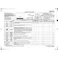
SECTION 3 ELECTRICAL ADJUSTMENTS
Note: Tool � 1/4 λ sleeve antenna
0 dBm = 1 mW, 0 dBV = 1 Vrms TX SECTION
1. Consumption Current Check Setting:
regulated dc power supply battery terminal 3 mA Set
Production procedure: 1. Cut about 80 mm of the outer cover at the other end of an approximately 2 meter coaxial cable (1.5D-2V or the equivalent) with a BNC connector.
80 mm
BNC
+ �
2. Pull back the outer cover and fold the wire mesh over the outside cover.
battery terminal #
80 mm 80 mm BNC
3. Cover the folded back wire mesh (outer cover) with a tube (for example, heat shrink tube) and fasten.
Procedure: 1. Connect a regulated dc power supply (1.5 V) and ampere meter. 2. Check that the value of ampere meter satisfy specified value. Specified value: 70 mA to 80 mA
BNC
2. TX Frequency Confirmation Setting:
The WCS-999 is a wireless microphone system operating in the 900 MHz. This system comprises the transmitter unit and the receiver unit.
TX BASE board
frequency counter
1/4 λ sleeve antenna lead wire antenna (ANT1)
Procedure: 1. Connect the 1/4 λ sleeve antenna to a frequency counter, and put the antenna by the lead wire antenna (ANT1). 2. Set the [RF CHANNEL] switch (SW51) to[1]. 3. Confirm that the value of frequency counter satisfy specified value. 4. Change the [RF CHANNEL] switch (SW51) to [2]. 5. Confirm that the value of frequency counter satisfy specified value. 6. Change the [RF CHANNEL] switch (SW51) to [3]. 7. Confirm that the value of frequency counter satisfy specified value. Specified values: CH-1: 912.78 MHz to 912.92 MHz CH-2: 913.68 MHz to 913.82 MHz CH-3: 914.28 MHz to 914.42 MHz
�6�
|