|
|
|
Productos
|
|
Información
|
|
Destacado
|
|
|
 |
|
|
No hay comentarios de productos.
VL-Z100S-S/H-S/E-S VL-Z300S-S/H-S/E-S
6. ADJUSTING AND CHECKING OF MECHANISM
The items described here are relevant to the general on-site servicing (field service). This section does not cover adjustment and replacement for which sophisticated equipment, jigs and techniques are required. In order to maintain the initial characteristics of the mechanism, it is necessary to perform maintenance and inspection and also it is essential not to damage the tape etc. In the case of an adjustment that requires a jig, be sure to use the specified jig. <Caution> (1) When adjusting and checking the mechanism, be sure to see that the power supply and the status are as indicated in Caution on the title. (2) Do not apply external voltage to the loading motor with the mechanism connected with the main circuit board. (Doing so could cause a failure.) (3) When running the tape, be sure to do so with the cassette controller assembly installed.
6-1. Checking of PB (REC) winding torque
AC adapter used, Cassette controller assembly installed (1) Set the torque cassette with the cassette controller installed in the mechanism. In the SP record mode (or in the PB mode if signals have been SP-recorded on the tape), check that the winding torque is within spec. <Spec for PB (REC) winding torque>(If there is a torque ripple, read the center value.) 0.7+0.2/-0.05N·m, Ripple: 0.1mN·m or less
6-2. Checking of VS-REW winding torque
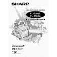
AC adapter used, Cassette controller assembly not installed (Mechanism only) (1) Remove the cassette controller, turn ON the down SW while referring to 8-3, operate in the test mode (T01) and select the VS-REW mode. (2) Set the torque gauge in the S reel table, push the tip of the tension pole with your finger in the direction shown by Arrow A to release the tension band, and check that the winding torque is within spec. (Fig.1) (Do not apply the own weight of the torque gauge or rotate it during measurement.) <Spec for VS-REW winding torque> (If there is a torque ripple, read the center value.) 1.5 ± 0.15N·m, Ripple: 0.15mN·m or less (3) After checking the winding torque, remove the torque gauge and turn OFF the down SW. The mechanism will automatically go into the standby mode.
(3)
2.4±0.1
Fig.1 How to release the tension band when measuring the
2.4±0.1
VS-REW winding torque
Set value of height of reel table
6-3. Checking of height of reel table
3 to 4V DC, Cassette controller assembly not installed (Mechanism only) (1) Remove the cassette controller. (Refer to 8-2.) (2) Apply 3 to 4V DC to the loading motor while referring to 8-1 and select the PB mode. (3) Fit the holes of the master plane to the two guides (portions A and B) shown in the Fig.2, taking great care not to allow master plane to strike the running parts such as the drum and guide roller or the MIC contact. (4) Using a pair of vernier calipers etc., measure the heights of the reel-supporting faces of the S reel table and Tu reel table from the top face of the master plane and check that the measured heights satisfy the set values. (Fig.3) When measuring the height of the S reel table, push the tip of the tension pole with your finger in the direction shown by Arrow A to release the tension band. (Fig.1) (5) If the measured height does not satisfy the set value, replace the reel table and make checking again. <Note> After replacement, select the L start mode (see 8-1) and check that the reel table rotates smoothly.
Reel-supporting face
A
B
MIC contact Fig.2 Checking of reel table
Set value of height of reel table
Fig.3
10
|
|
|
> |
|