|
|
|
Productos
|
|
Información
|
|
Destacado
|
|
|
 |
|
|
No hay comentarios de productos.
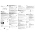
VL-PD6S/H/E
3. DISASSEMBLY OF THE SET
Note: Before removing the cabinet, turn off the power supply, and ascertain that the battery have been removed. 1.
LCD monitor lock release button Top cover
4.
(Q)
(A)
�
Zoom microphone terminal PWB
� Press the LCD monitor lock release button, and open the LCD by 90�. � While the LCD monitor lock release lever is pulled up, move the LCD remote control horizontally and lift it up to remove it. (Move the LCD remote control in the direction of the arrow A.)
2.
� After the V/F section is pulled out and is turned, remove the three screws ((Q)XiPSN17P03000) on the shoe fitting. Then, slide the top cover and lift it up to remove it. � Remove the one screw ((A)LX-BZ0192TAFF) to remove the zoom microphone terminal PWB.
5.
V/F section
(P) (P) (R) (P)
� Remove the four screws ((P)XiPSF17P03000) on the bottom cover to remove the bottom cover. � Remove the connector of the card and the connector of the zoom unit on the bottom.
(P) (P) Battery cover
3.
(Q)
� Lift up the V/F section, and remove the four screws ((P)XiPSF17P03000), the one screw ((R)XiPSF17P04000) to remove the battery cover. � Remove the connector of the battery terminal and the connector of the power SW.
6.
(P)
(P)
(P)
(Q)
(Q) Claw Front cover (P) (G)
� Remove the three screws ((Q)XiPSN17P03000) and the two screws ((P)XiPSF17P03000) on the front cover to remove the front cover. Note:Be careful that the claw on the front cover engages with cassette lid. � Remove two sheets of FPC of the eject, zoom microphone and AV terminal unit.
� Remove the one screw ((Q)XiPSN17P03000), one screw ((G)LX-HZ0050TAFF) and open the cassette lid. Then, remove the three screws ((P)XiPSF17P03000) on the both ends and in the center. � Remove each connector of the eject switch, H/A, zoom unit, and card socket unit.
4
|
|
 |
> |
|
