|
No hay comentarios de productos.
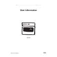
3.3.6 Removing the amp. board (See Fig.10) � Prior to performing the following procedures, remove the amplifier assembly, rear panel, heat sink BKT and mother board. (1) From the left side of the amplifier assembly, remove the nine screws J attaching the amp. board. (2) Take out the amp. board with the heat sink.
Amp. board
Heat sink
J
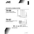
Fig.10 3.3.7 Removing the heat sink (See Figs.11 and 12) � Prior to performing the following procedures, remove the amplifier assembly, rear panel, heat sink BKT, mother board and amp. board. (1) From left side of the amp. board, remove the screw K attaching the hold spring to the heat sink. (See Fig.11.) (2) Remove the four screws L attaching the power IC to the heat sink. (See Fig.11.) (3) From the reverse side of the amp. board, remove the three screws M attaching the heat sink to the amp. board. (See Fig.12.) (4) Take out the heat sink. 3.3.8 Removing the power IC (See Fig. 12) � Prior to performing the following procedures, remove the amplifier assembly, rear panel, heat sink BKT, mother board, amp. board and heat sink. (1) From the reverse side of the amp. board, remove the solders from the solder points a on the amp. board. (2) Take out the power IC.
Heat sink
Power IC
Amp. board
L
Hold spring
Fig.11
L K
Amp. board
Solder points a
M
Fig.12
1-22 (No.MB236)
 $4.99 TH-S7 JVC
Manual de Usuario Manual del propietario completo en formato digital. El manual estará disponible para descarga como …
|