|
No hay comentarios de productos.
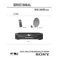
TH-A5R Removing the DVD mechanism assembly (See Fig.5 and 6)
Prior to performing the following procedure, remove the top cover. 1. Disconnect the card wire from the connector J14 and J21 on the DVD MPEG board. 2. Remove the two screws E attaching the DVD mechanism assembly and pull up with drawing out. 3. Disconnect the harness from the connector J2 on the DVD loader board.
DVD mechanism assembly DVD MPEG board
J14
E
J21
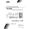
Removing the rear panel (See Fig.7 and 8)
Prior to performing the following procedure, remove the top cover and power cord. 1. Disconnect the harness from the connector NW11 on the DSP board. 2. Remove the two screws F, four screws G, and five screws I attaching the each boards to the rear panel. 3. Remove the three screws J attaching the rear panel on the back of the body.
Rear panel
Fig.5
DVD mechanism assembly
Removing the tuner pack (See Fig.7 and 8)
Prior to performing the following procedure, remove the top cover. 1. Disconnect the card wire from the connector CON01 on the tuner pack. 2. Remove the two screws F attaching the tuner pack to the rear panel. Fan motor
J2 DVD loader board
Fig.6 Rear panel
H
G
Removing the jack board (See Fig.7 and 8)
Prior to performing the following procedure, remove the top cover. 1. Disconnect the card wire from the connector VW2 on the jack board. 2. Remove the four screws G attaching the jack board to the rear panel. 3. Disconnect the connector VW1 on the jack board and pull up the jack board. DSP board
J
I
Fig.7
J
F
CON01
J
Removing the fan motor (See Fig.7 and 8)
Prior to performing the following procedures, remove the top cover . 1. Disconnect the harness from the connector NW11 on the DSP board . Rear panel 2. Removing the two screws H attaching the fan motor on the rear panel. VW1 Jack board VW2
NW11 (on the DSP board) Fig.8
Tuner pack
1-7
|