|
No hay comentarios de productos.
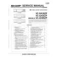
SECTION 2 DISASSEMBLY
Note: Follow the disassembly procedure in the numerical order given.
MAIN BOARD
1 two screws (P2 � 8)
4 main board
3 cabinet (rear)
2 four claws 2 two claws
5 cabinet (front)
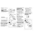
DIAL POINTER SETTING
Note: Follow the assembly procedure in the numerical order given.
pointer
1 Mount the pointer as shown in the figure A.
4 main board
fig. A
3 Turn CV1 fully in the arrow direction. 2 Mount the knob (TUNE) as shown in the figure B.
knob (TUNE) cabinet (front)
fig. B
�4�
|