|
No hay comentarios de productos.
SECTION 1 GENERAL
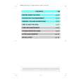
TABLE OF CONTENTS
This section is extracted from instruction manual.
Specifications ........................................................................... 1
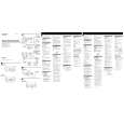
LOCATION AND FUNCTION OF CONTROLS
1. GENERAL
Location and Function of Controls .................................... 2
2. DISASSEMBLY
2-1. Cabinet (Lower) .......................................................... 3 2-2. Front panel .................................................................. 3 2-3. Main Board ................................................................. 4
3. DIAGRAMS
3-1. Printed Wiring Boards ................................................ 5 3-2. Schematic Diagram ..................................................... 7
4. EXPLODED VIEW ................................................. 9 5. ELECTRICAL PARTS LIST .................................... 10
Flexible Circuit Board Repairing � Keep the temperature of the soldering iron around 270°C during repairing. � Do not touch the soldering iron on the same conductor of the circuit board (within 3 times). � Be careful not to apply force on the conductor when soldering or unsoldering. Notes on chip component replacement � Never reuse a disconnected chip component. � Notice that the minus side of a tantalum capacitor may be damaged by heat.
�2�
|