Su carrito de compras está vacío
 
English Polski Spanish 
Buscar un manual
 

(p.Ej. AA-V20EG JVC, ZX-7 Sony)
PayPal 1000+ rating Secure, Encrypted Checkout.
 
Usuarios conectados
Actualmente hay 5944 visitantes online.
Productos
Información
Destacado
Inicio >> SONY >> SAT-HD100 Manual de Servicio
 
 0 artículo(s) en Su carrito 

SONY SAT-HD100
Manual de Servicio


¡Twitee acerca de este producto y obtenga $1.00 de crédito en la tienda para uso!
  • Contiene diagramas del circuito
  • Descargable
  • Formato PDF
  • Manual completo
  • Idiomas: English
Precio: $4.99

Descripción del SONY SAT-HD100 Manual de Servicio

Manual de servicio completo en formato digital (archivo PDF). Los manuales de servicio por lo general contienen diagramas de circuitos, tarjetas de circuitos impresos, consejos para reparación, diagramas de cableado, diagramas de bloque y lista de refacciones. El Manual de Servicio (a veces llamado Manual de Reparación) es usado principalmente por los técnicos.

Si tan solo quiere saber cómo utilizar su televisión, reproductor de vídeo, reproductor de mp3, etc. Quizá lo que necesita es el Manual del Propietario. Después de colocar la orden le enviaremos las instrucciones de descarga a su dirección de e-mail.

The manual is available in languages: English

Not yet ready
You must purchase it first

Opiniones de los clientes
No hay comentarios de productos.

TEXT_PDF_SNIPPET
SAT-HD100

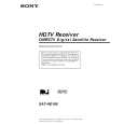
1-4. A, G & TU BOARD REMOVAL

4

5

6

7

8

9

3

2 1
Note: For board removal or replacement, detach all attached cables, and leave them attached to an existing board.

10 11

7

1 2 3

Detach the connector between the A and G Boards. Remove (2) screws (+BVTT 3 x 12) from G Board. Remove (1) screw (+BVTP 3 x 8) from G Board. Gently lift the board forward and up to remove. Remove (1) screw (M3 x 6) from the back panel holding in the tuning unit. Remove (2) hex nuts from the cable jacks. Remove (2) screws (+BVTP 3 x 8) from the back of the unit, mounting the fan assembly. Lift the assembly up and out to remove.

Remove (2) screws (M3 x 6) from the back of the unit, mounting the RF Remote Assembly. Lift the assembly up and out to remove. Remove (2) screws (+BVTP 3 x 8) from the back of the unit at the RCA jacks. Remove (2) screws (+BVTT 3 x 12) mounting the TU Board to chassis. Remove (4) screws (+BVTT 3 x 12) mounting A Board to Chassis. Gently lift the A and TU Boards simultaneously forward and up to remove. Support the weight of both boards at the connector. Once removed from the chassis, disconnect the connector shown to separate the A and TU Boards.

8

4 5 6

�8�

Quizás también quiera comprar

$4.99

SATHD100 SONY
Manual de Usuario

Manual del propietario completo en formato digital. El manual estará disponible para descarga como …
>
Parse Time: 0.219 - Number of Queries: 102 - Query Time: 0.056