Su carrito de compras está vacío
 
English Polski Spanish 
Buscar un manual
 

(p.Ej. AA-V20EG JVC, ZX-7 Sony)
PayPal 1000+ rating Secure, Encrypted Checkout.
 
Usuarios conectados
Actualmente hay 5887 visitantes online.
Productos
Información
Destacado
Inicio >> JVC >> RX5032VSL Manual de Servicio
 
 0 artículo(s) en Su carrito 

JVC RX5032VSL
Manual de Servicio


¡Twitee acerca de este producto y obtenga $1.00 de crédito en la tienda para uso!
  • Contiene diagramas del circuito
  • Descargable
  • Formato PDF
  • Manual completo
  • Idiomas: English
Precio: $4.99

Descripción del JVC RX5032VSL Manual de Servicio

Manual de servicio completo en formato digital (archivo PDF). Los manuales de servicio por lo general contienen diagramas de circuitos, tarjetas de circuitos impresos, consejos para reparación, diagramas de cableado, diagramas de bloque y lista de refacciones. El Manual de Servicio (a veces llamado Manual de Reparación) es usado principalmente por los técnicos.

Si tan solo quiere saber cómo utilizar su televisión, reproductor de vídeo, reproductor de mp3, etc. Quizá lo que necesita es el Manual del Propietario. Después de colocar la orden le enviaremos las instrucciones de descarga a su dirección de e-mail.

The manual is available in languages:

Not yet ready
You must purchase it first

Opiniones de los clientes
No hay comentarios de productos.

TEXT_PDF_SNIPPET
RX-5032VSL

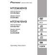
2.7 Removing the speaker terminal board (See Fig.8) � Prior to performing the following procedure, remove the top cover and rear panel. (1) From the top side of the main body, remove the solders from the soldered sections a on the speaker terminal board.

Parallel wires

Soldered sections a Speaker terminal board Fig.8
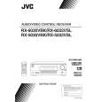
2.8 Removing the main board (See Fig.9) � Prior to performing the following procedure, remove the top cover. (1) From the top side of the main body, remove the tie bands fixing the wires. (2) Remove the tie band and wire protection board fixing the card wire. (3) Remove the solders from the soldered section b on the (4) (5) (6) (7) (8) (9) speaker terminal board attaching the parallel wires. Disconnect the relay board from the connectors (CN291, CN491) on the power supply board and audio board. Disconnect the parallel wire from the connector CN241 on the power supply board. Disconnect the wire from the connector CN251 on the power transformer board 1. Disconnect the wires from the connectors CN471, CN472 and CN473 on the audio board. Remove the screw H, two screws J and four screws K attaching the main board. Take out the main board.
Relay board Tie bands K Main board K Tie band Tie band Wire protection board CN251 CN291 Power transformer board 1 Power supply board CN241

K

J
Card wire CN473

Power transformer

H

CN472 Audio Parallel wires board CN471 CN491 Speaker terminal board Soldered section b

Fig.9

(No.22028)1-7

Quizás también quiera comprar

$4.99

RX5032VSL JVC
Manual de Usuario

Manual del propietario completo en formato digital. El manual estará disponible para descarga como …
>
Parse Time: 0.724 - Number of Queries: 100 - Query Time: 0.358