|
|
|
Productos
|
|
Información
|
|
Destacado
|
|
|
 |
|
|
No hay comentarios de productos.
FUNCTION OF IMPORTANT COMPONENTS
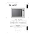
DOOR OPEN MECHANISM The door can be opened by pulling the door.
FUSE F2
1. The fuse F2 also blows when the H.V. rectifer, H.V. wire harness, H.V. capacitor, magnetron or secondary winding of power transformer is shorted. 2. If the wire harness or electrical components are shortcircuited, the fuse F2 blows to prevent an electric shock or fire hazard.
Door Latch hook
THERMAL CUT-OUT 145°C TC01 (OVEN)
SW3: Stop switch
SW2: Monitor switch
SW1:Monitored latch switch
The thermal cut-out located on the top of the oven cavity is designed to prevent damage to the oven if the foods in the oven catch fire due to over heating produced by improper setting of cook time or failure of control unit. Under normal operation, the oven thermal cut-out remains closed. However, when abnormally high temperatures are reached within the oven cavity, the oven thermal cut-out will open at 145°C, causing the oven to shut down. When the temperature of the cut-out falls to below 115°C it's contacts will reset(close).
Latch heads
THERMAL CUT-OUT 125°C TC02 (MG)
This thermal cut-out protects the magnetron against overheat. If the temperature goes up higher than 125°C because the fan motor is interrupted or the ventilation openings are blocked, the thermal cut-out TC02 will open and line voltage to the high voltage transformer T will cut off and operation of the magnetron MG will be stopped. The defective thermal cut-out must be replaced with a new one.
Figure D-1. Door Open Mechanism
MONITORED LATCH SWITCH (SW1)
1. When the oven door is closed, the contacts (COM - NO) must be closed. 2. When the oven door is opened, the contacts (COM - NO) must be opened.
TURNTABLE MOTOR
The turntable motor drives the turntable roller assembly to rotate the turntable.
MONITOR SWITCH (SW2)
1. When the oven door is closed, the contacts (COM - NC) must be opened. 2. When the oven door is opened, the contacts (COM NC) must be closed. 3. If the oven door is opened and the contacts (COM - NO) of the monitored latch switch (SW1) fail to open, fuse F8A blows simultaneously with closing the contacts (COM - NC) of the monitor switch (SW2).
FAN MOTOR
The fan motor drives a blade which draws external cool air. This cool air is directed through the air vanes surrounding the magnetron and cools the magnetron. This air flows through the oven cavity to remove steam and vapors given off from the heating foods. It is then vented through the exhaust air vents at the rear of oven cavity.
STOP SWITCH (SW3)
1. When the oven door is closed, the contacts (COM - NO) must be closed. 2. When the oven door is opened, the contacts (COM - NO) must be opened. CAUTION: BEFORE REPLACING A BLOWN FUSE (F1) TEST THE MONITORED LATCH SWITCH (SW1) AND MONITOR SWITCH (SW2) FOR PROPER OPERATION. (REFER TO CHAPTER "TEST PROCEDURE".)
NOISE FILTER
The noise filter prevents the radio frequency interference that might flow back in the power circuit.
SPECIAL FUSE F1 20A
If the wire harness or electrical components are shortcircuited, this fuse F1 blows to prevent an electric shock or fire hazard.
R-61FBST/R-62FBST - 10
|
|
|
> |
|