|
|
|
Productos
|
|
Información
|
|
Destacado
|
|
|
 |
|
|
No hay comentarios de productos.
MZ-B10
Rewriting the NV values
Note : Modify four adjusted values through the following procedure. Modifying the item number 863 and 864 is not necessary after version 1.600. � Adjusted values modifying procedure 1. Select manual mode of the test mode, and set item number 860 (see page 16). 2. Press the > key to set item number 861.
Set LCD display
Power Supply Manual Adjustment
� Adjustment sequence Adjustment must be done with the following steps. 1. VC1_LOW (PB) adjustment (item number : 741) 2. VC1_HIGH (REC) adjustment (item number : 742) 3. VC2_LOW adjustment (item number : 743) 4. VC2_HIGH adjustment (item number : 744) 5. REG1 adjustment (item number : 745) 6. REG3_LOW1 adjustment (item number : 747) 7. REG3_LOW2 adjustment (item number : 748) 8. REG3_HIGH adjustment (item number : 749) 9. VREC_LOW (X2 speed) adjustment (item number : 751) 10. VREC_MIDDLE (X4 speed)adjustment (item number : 752) 11. VREC_HIGH (HEAD MOTOR) adjustment (item number : 753) � Setting Method of Power Supply Manual Adjustment 1. Make sure that the power supply voltage is 1.2V (BATT IN). 2. Select the manual mode of the test mode (see page 16). 3. Set item number.
Note1: BATT- terminal is not GND when AC adaptor is used. Note2: Power supply adjustment auto item feed mode (page 26) is available to perform the temperature Correction and Power Supply Adjustment without entering the manual mode.
V1 num ** 861
**: Adjusted value
3. Adjust with the [SPEED CONTROL +] key (adjusted value up) or [SPEED CONTROL -] key (adjusted value down) so that the adjusted value becomes E3. 4. Press the X key on the set or the key on the remote commander to write the adjusted value. 5. Press the > key to set item number 862.
Set LCD display
V1 dat ** 862
**: Adjusted value
� Adjustment Method of VC1_LOW (PB) (item number: 741)
Set LCD display
VC1 L
** 741
6. Adjust with the [SPEED CONTROL +] key (adjusted value up) or [SPEED CONTROL -] key (adjusted value down) so that the adjusted value becomes 55. 7. Press the X key on the set or the key on the remote commander to write the adjusted value. 8. Press the > key to set item number 863.
Set LCD display
**: Adjusted value
V2 num ** 863
**: Adjusted value
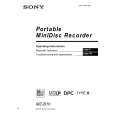
1. Connect a digital voltmeter to the TP1928 (VCO1) on the MAIN board, and adjust [SPEED CONTROL +] key (voltage up) or [SPEED CONTROL --] key (voltage down) so that the voltage becomes 2.4 ± 0.05V.
digital voltmeter MAIN board TP1928 (VCO1) TP1616 (GND)
9. Adjust with the [SPEED CONTROL +] key (adjusted value up) or [SPEED CONTROL -] key (adjusted value down) so that the adjusted value becomes 89. 10. Press the X key on the set or the key on the remote commander to write the adjusted value. 11. Press the > key to set item number 864 .
Set LCD display
2. Press the X key on the set or the commander to write the adjusted value.
key on the remote
V2 dat ** 864
**: Adjusted value
Adjustment and Connection Location: MAIN board (see page 25)
12. Adjust with the [SPEED CONTROL +] key (adjusted value up) or [SPEED CONTROL -] key (adjusted value down) so that the adjusted value becomes 03. 13. Press the X key on the set or the key on the remote commander to write the adjusted value.
21
|
|
|
> |
|