Su carrito de compras está vacío
 
English Polski Spanish 
Buscar un manual
 

(p.Ej. AA-V20EG JVC, ZX-7 Sony)
PayPal 1000+ rating Secure, Encrypted Checkout.
 
Usuarios conectados
Actualmente hay 5668 visitantes online.
Productos
Información
Destacado
Inicio >> JVC >> MXGT700 Manual de Servicio
 
 0 artículo(s) en Su carrito 

JVC MXGT700
Manual de Servicio


¡Twitee acerca de este producto y obtenga $1.00 de crédito en la tienda para uso!
  • Contiene diagramas del circuito
  • Descargable
  • Formato PDF
  • Manual completo
  • Idiomas: English
Precio: $4.99

Descripción del JVC MXGT700 Manual de Servicio

Manual de servicio completo en formato digital (archivo PDF). Los manuales de servicio por lo general contienen diagramas de circuitos, tarjetas de circuitos impresos, consejos para reparación, diagramas de cableado, diagramas de bloque y lista de refacciones. El Manual de Servicio (a veces llamado Manual de Reparación) es usado principalmente por los técnicos.

Si tan solo quiere saber cómo utilizar su televisión, reproductor de vídeo, reproductor de mp3, etc. Quizá lo que necesita es el Manual del Propietario. Después de colocar la orden le enviaremos las instrucciones de descarga a su dirección de e-mail.

The manual is available in languages:

Not yet ready
You must purchase it first

Opiniones de los clientes
No hay comentarios de productos.

TEXT_PDF_SNIPPET
MX-GT700

Removing the heat sink & amp. board (See Fig.8, 11 and 12)
Prior to performing the following procedure, remove the metal cover and CD changer unit. 1. Disconnect the card wire from the connector ACW1 and the harness from the connector ACW2, ACW5 and ACW6 on the amp. board. 2. Remove the four screws I attaching the heat sink cover to the rear panel. Remove the heat sink cover. 3. Remove the four screws J attaching the heat sink and two screws K attaching the speaker terminal to the rear panel. 4. After moving the heat sink upward, remove the claws. Then pull out the heat sink & amp. board inward. If the voice board is removed at this time, it will be able to work comfortably.
Heat sink cover

Joint2

(Bottom side)

H

Fig.10
Rear panel

I

I
Removing the fan motor (See Fig.8 and 12)
Prior to performing the following procedure, remove the metal cover and heat sink cover.
1. Disconnect the harness from the connector ACW5 on the amp. board. Fig.11

L J

Rear panel

2. Remove the two screws L attaching the fan motor Claws to the rear panel. Heat sink

M N K

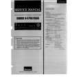
Removing the tuner board (See Fig.12 and 13)
Prior to performing the following procedure, remove the metal cover. 1. Disconnect the card wire from the connector CON01 on the tuner board. 2. Remove the two screws M attaching the tuner board to the rear panel.

J

Speaker terminal

O P
Fig.12
Main board CON01 Rear panel

Tuner board

Removing the rear panel

(See Fig.12)

Prior to performing the following procedure, remove the metal cover, CD changer unit, heat sink & amp. board and tuner board. 1. Remove the two screws N, screw O and three screws P attaching the rear panel.

Fig.13
1-7

Quizás también quiera comprar

$4.99

MX-GT700 JVC
Diagrama del circuito

Conjunto de diagramas del circuito. Los diagramas serán proporcionados en un archivo PDF. El archiv…

$4.99

MXGT700 JVC
Manual de Usuario

Manual del propietario completo en formato digital. El manual estará disponible para descarga como …

$4.99

MX-GT700 JVC
Catálogo de piezas

Únicamente Catálogo de Partes. Está disponible en formato PDF. Muy útil si su equipo se ha averi…
>
Parse Time: 0.2 - Number of Queries: 106 - Query Time: 0.048