Su carrito de compras está vacío
 
English Polski Spanish 
Buscar un manual
 

(p.Ej. AA-V20EG JVC, ZX-7 Sony)
PayPal 1000+ rating Secure, Encrypted Checkout.
 
Usuarios conectados
Actualmente hay 6043 visitantes online.
Productos
Información
Destacado
Inicio >> PIONEER >> MJ-D707/KU Manual de Servicio
 
 0 artículo(s) en Su carrito 

PIONEER MJ-D707/KU
Manual de Servicio


¡Twitee acerca de este producto y obtenga $1.00 de crédito en la tienda para uso!
  • Contiene diagramas del circuito
  • Descargable
  • Formato PDF
  • Manual completo
  • Idiomas: English
Precio: $4.99

Descripción del PIONEER MJ-D707/KU Manual de Servicio

Manual de servicio completo en formato digital (archivo PDF). Los manuales de servicio por lo general contienen diagramas de circuitos, tarjetas de circuitos impresos, consejos para reparación, diagramas de cableado, diagramas de bloque y lista de refacciones. El Manual de Servicio (a veces llamado Manual de Reparación) es usado principalmente por los técnicos.

Si tan solo quiere saber cómo utilizar su televisión, reproductor de vídeo, reproductor de mp3, etc. Quizá lo que necesita es el Manual del Propietario. Después de colocar la orden le enviaremos las instrucciones de descarga a su dirección de e-mail.

The manual is available in languages: English

Not yet ready
You must purchase it first

Opiniones de los clientes
No hay comentarios de productos.

TEXT_PDF_SNIPPET
MJ-D707, MJ-17D

7.2 DIAGNOSIS
7.2.1 DISASSEMBLY Removal of the Servo Mechanism Assy
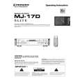
1 Remove the screw A. 2 Disconnect the connectors (CN102, CN103, CN105), open the hook of part A, and tilt the upper side of the CORE MAIN UNIT ASSY to the front. CN105 3 Disconnect the connector (CN101) at the rear of the CORE MAIN UNIT ASSY and remove the CORE MAIN UNIT ASSY. 4 After the Carrier has been pushed in, move the Upper Slider to Screw A the rear and stop it at the position where the Under Slider starts to move.

2

CN103

1

2
CN101

Part A

CN102

4
Rear Side

Upper Slider

2

3

CORE MAIN UNIT ASSY

Carrier

Move

5 Shift part B to the position shown in the figure while raising the Under Slider. (At the same time, the Upper Slider moves to the front.) 6 Remove the Lock Plate. (One screw B)

Under Slider

Under Slider Upper Slider

5

Part B

7 Remove the Servo Mechanism Assy.

Screw B

6

Lock Plate

Servo Mechanism Assy

Caution for the time of installation of the servo mechanism assy
Move the MD Pick-up to the innermost circumference. After installation of the servo mechanism assembly, shift the Upper Slider to the rear. (The Under Slider moves at the same time, and the servo mechanism assy is fixed. When the Under Slider is slide, this becomes the reason for switching ring catching.)

7
61

Quizás también quiera comprar

$4.99

MJ-D707/KU PIONEER
Manual de Usuario

Manual del propietario completo en formato digital. El manual estará disponible para descarga como …
>
Parse Time: 0.159 - Number of Queries: 103 - Query Time: 0.038