|
No hay comentarios de productos.
KS-AX4500
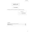
5. Remove the 13 screws E retaining the panels on both sides of the main unit.
E
Rear panel
E E
Fig. 5
Front panel
E
Fig. 6
F
6. Remove the 14 screws F attaching the MAIN PCB to the bottom of the main unit.
F
F
Fig. 7
MAIN PCB
MAIN PCB
7. Remove the MAIN PCB by lift up the arrow mark.
(Side view)
Fig. 8
1-6
|