- SAFETY INFORMATION
- EXPLODED VIEWS AND PARTS LIST
- BLOCK DIAGRAM AND SCHEMATIC DIAGRAM
- PCB CONNECTION DIAGRAM
- ELECTRICAL PARTS LIST
- ADJUSTMENT
- GENERAL INFORMATION
- DIAGNOSIS
- DISASSEMBLY
- CONNECTOR FUNCTION DESCRIPTION
- PARTS
- IC
- DISPLAY
- OPERATIONAL FLOW CHART
- OPERATIONS AND SPECIFICATIONS
No hay comentarios de productos.
KEH-P5010R,P5011,4011
7 GENERAL INFORMATION
7.1 DIAGNOSIS 7.1.1 DISASSEMBLY
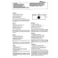
- Removing the Case (not shown) 1. Remove the two screws. 2. Remove the Case. - Removing the Cassette Mechanism Module (Fig.1) Remove the four screws and then remove the Cassette Mechanism Module. - Removing the Panel Assy (Fig.1) Disconnect the two stoppers and then remove the Panel Assy.
Cassette Mechanism Module
Panel Assy
Fig.1
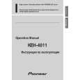
- Removing the Tuner Amp Unit (Fig.2) Remove the two screws. Straight the tabs at four locations indicated. Remove the screw. Remove the three screws and then remove the Tuner Amp Unit.
Tuner Amp Unit
Fig.2
54
|