Su carrito de compras está vacío
 
English Polski Spanish 
Buscar un manual
 

(p.Ej. AA-V20EG JVC, ZX-7 Sony)
PayPal 1000+ rating Secure, Encrypted Checkout.
 
Usuarios conectados
Actualmente hay 5985 visitantes online.
Productos
Información
Destacado
Inicio >> JVC >> KD-G200 Manual de Servicio
 
 0 artículo(s) en Su carrito 

JVC KD-G200
Manual de Servicio


¡Twitee acerca de este producto y obtenga $1.00 de crédito en la tienda para uso!
  • Contiene diagramas del circuito
  • Descargable
  • Formato PDF
  • Manual completo
  • Idiomas: English
Precio: $4.99

Descripción del JVC KD-G200 Manual de Servicio

Manual de servicio completo en formato digital (archivo PDF). Los manuales de servicio por lo general contienen diagramas de circuitos, tarjetas de circuitos impresos, consejos para reparación, diagramas de cableado, diagramas de bloque y lista de refacciones. El Manual de Servicio (a veces llamado Manual de Reparación) es usado principalmente por los técnicos.

Si tan solo quiere saber cómo utilizar su televisión, reproductor de vídeo, reproductor de mp3, etc. Quizá lo que necesita es el Manual del Propietario. Después de colocar la orden le enviaremos las instrucciones de descarga a su dirección de e-mail.

The manual is available in languages: English

Not yet ready
You must purchase it first

Opiniones de los clientes
No hay comentarios de productos.

TEXT_PDF_SNIPPET
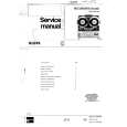
3.1.4 Removing the side panel (See Fig.4) � Prior to performing the following procedure, remove the front panel assembly as required. (1) Remove the screw B and two screws C attaching the heat sink on the left side of the main body, and remove the side panel.

C

B

C

Side panel
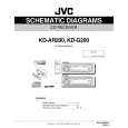
Fig.4 3.1.5 Removing the rear bracket (See Fig.5) � Prior to performing the following procedure, remove the bottom cover. (1) Remove the three screws D, three screws E and two screws F attaching the rear bracket on the back side of the main body. (2) Remove the rear bracket.

E

F
Rear bracket

E

F

D
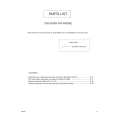
Fig.5 3.1.6 Removing the main board (See Fig.6) � Prior to performing the following procedure, remove the front panel assembly, front chassis assembly, side panel, bottom cover and rear bracket. (1) Remove the two screws G attaching the main board. (2) Disconnect the connector CN501 and remove the main board.

D

Main board CN501

G

G

Fig.6

(No.MA030)1-7

Quizás también quiera comprar

$4.99

KD-G200 JVC
Diagrama del circuito

Conjunto de diagramas del circuito. Los diagramas serán proporcionados en un archivo PDF. El archiv…

$4.99

KD-G200 JVC
Catálogo de piezas

Únicamente Catálogo de Partes. Está disponible en formato PDF. Muy útil si su equipo se ha averi…
>
Parse Time: 0.156 - Number of Queries: 102 - Query Time: 0.038