|
No hay comentarios de productos.
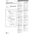
SECTION 3 DIAL POINTER SETTING
Note: Follow the assembly procedure in the numerical order given.
7 Turn CV1 and RV1 shaft in the arrow direction fully. 8 RADIO board
CV1
RV1
2 Set the pointer to the guide line.
RADIO board (Conductor Side)
3 chassis 4 screw (P3 � 10)
pointer
guide line
knob (TUNE)
marking A
knob (VOL)
1 pointer
marking B
6 speaker 5 As shown in figure, marking A of TUNE knob and marking B of VOL knob setting.
�4�
|