Su carrito de compras está vacío
 
English Polski Spanish 
Buscar un manual
 

(p.Ej. AA-V20EG JVC, ZX-7 Sony)
PayPal 1000+ rating Secure, Encrypted Checkout.
 
Usuarios conectados
Actualmente hay 5222 visitantes online.
Productos
Información
Destacado
Inicio >> JVC >> HXGD8 Manual de Servicio
 
 0 artículo(s) en Su carrito 

JVC HXGD8
Manual de Servicio


¡Twitee acerca de este producto y obtenga $1.00 de crédito en la tienda para uso!
  • Contiene diagramas del circuito
  • Descargable
  • Formato PDF
  • Manual completo
  • Idiomas: English
Precio: $4.99

Descripción del JVC HXGD8 Manual de Servicio

Manual de servicio completo en formato digital (archivo PDF). Los manuales de servicio por lo general contienen diagramas de circuitos, tarjetas de circuitos impresos, consejos para reparación, diagramas de cableado, diagramas de bloque y lista de refacciones. El Manual de Servicio (a veces llamado Manual de Reparación) es usado principalmente por los técnicos.

Si tan solo quiere saber cómo utilizar su televisión, reproductor de vídeo, reproductor de mp3, etc. Quizá lo que necesita es el Manual del Propietario. Después de colocar la orden le enviaremos las instrucciones de descarga a su dirección de e-mail.

The manual is available in languages:

Not yet ready
You must purchase it first

Opiniones de los clientes
No hay comentarios de productos.

TEXT_PDF_SNIPPET
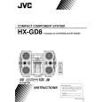
3.1.5 Removing the rear panel (See Figs.10 to 12) � Prior to performing the following procedures, remove the metal cover. (1) From the top side of the main body, remove the tie band bundling the wires. (See Fig.10.) Reference: After reassembling, bundle the wires with the new tie band as before. (See Fig.10.) Disconnect the wire from the connector CN202 on the bridge board. (See Fig.10.) From the back side of the main body, remove the two screws G and screw H attaching the rear cover. (See Fig.11.) Release the sections c and remove the rear cover. (See Fig.11.) Remove the sixteen screws J attaching the rear panel. (See Fig.12.) From the both sides of the main body, release the joints d attaching the rear panel to the chassis base and remove the rear panel with the fan. (See Fig.12.)

Tie band Bridge board

CN202 Wires

(2) (3)

(4) (5) (6)

3.1.6 Removing the fan (See Figs.10 to 12) � Prior to performing the following procedures, remove the metal cover. (1) From the top side of the main body, remove the tie band bundling the wires. (See Fig.10.) Reference: After reassembling, bundle the wires with the new tie band as before. (See Fig.10.) Disconnect the wire from the connector CN202 on the bridge board. (See Fig.10.) From the back side of the main body, remove the two screws G and screw H attaching the rear cover. (See Fig.11.) Remove the two screws K attaching the fan. (See Fig.12.) Take out the fan from the main body.

Fig.10

G

(2) (3)

H
c c

(4) (5)

c
Fig.11

Rear cover

Rear panel

J

J

Fan

K

K

J
d

J J
Fig.12

d

1-10 (No.MB188)

Quizás también quiera comprar

$4.99

HX-GD8 JVC
Manual de Usuario

Manual del propietario completo en formato digital. El manual estará disponible para descarga como …
>
Parse Time: 0.146 - Number of Queries: 103 - Query Time: 0.035