|
|
|
Productos
|
|
Información
|
|
Destacado
|
|
|
 |
|
|
No hay comentarios de productos.
NiCd
B6
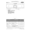
R11 NiMH B1 B2 T1 a b c SK2 D3a D2 R1 Re1 D6 Disn Pwrs Iosc
R5 R6 R7
B6 TS4 B3 B4 B5 B7 D2
D5
R8 R9 Vin Vcc En TS3 IC1 Enn Ledn Sco Scan Sci Rreo Duty Dis Mains Gnd Ncel Rref Ctim IC2 Full Emp Vcc C5 D3b
D8 C8
C2
L1 Upc Vac Moo Vbli Vbr Tacc Tamb Smot Eoo TS2 C6 R4 C3
A1 4/5A NiCd
B8
SK2c-a 200-240V SK2c-b 100-130V B1 power plug B2 rectifier B3 electronic on/off switch B4 up-converter B5 motor control B6 charging circuit B7 battery B8 motor
Rs Rd Rc
C4
Sel Gnd
PM D4
R2
R3
C1 SK1
TS1
B6. Charging circuit As NiMH batteries may not be continuously loaded with a high charging current, the HQ564 has a timer IC (IC1). This IC controls TS4 in such a way that a current of 200 mA is supplied to the battery for about 8 hours, after which TS4 switches to a trickle charging current of 25 mA. D5 and D6 suppress high voltage peaks. This circuit is not required in the HQ563 because in this shaver the NiCd battery is continuously charged at 200 mA via R11. The value of R11 equals the internal resistance of TS4. B7. Battery The 4/5A NiCd battery of the HQ563 has a capacity of 1200mAH. The capacity of the AA NiMH battery of the HQ564 is 1100 mAH. B8. Motor The motor is of the permanent magnet type. Zener diode D4 suppresses high voltage peaks during shaving. Normally, this diode is placed between the motor solder tags to suppress radio interference (RIF) in the mains as well. As TS1 makes it impossible to switch the motor on when the shaver is connected to the mains, D4 is now placed on the PCB. GENERAL Some resistors are not indicated in the electrical diagram. These are resistors of 0 ½ which serve as jumpers across print tracks or as interconnectors between the layers of the double-layer PCB.
|
|
|
> |
|