Su carrito de compras está vacío
 
English Polski Spanish 
Buscar un manual
 

(p.Ej. AA-V20EG JVC, ZX-7 Sony)
PayPal 1000+ rating Secure, Encrypted Checkout.
 
Usuarios conectados
Actualmente hay 5786 visitantes online.
Productos
Información
Destacado
Inicio >> SONY >> HDCA-701 Manual de Servicio
 
 0 artículo(s) en Su carrito 

SONY HDCA-701
Manual de Servicio


¡Twitee acerca de este producto y obtenga $1.00 de crédito en la tienda para uso!
  • Contiene diagramas del circuito
  • Descargable
  • Formato PDF
  • Manual completo
  • Idiomas: English
Precio: $4.99

Descripción del SONY HDCA-701 Manual de Servicio

Manual de servicio completo en formato digital (archivo PDF). Los manuales de servicio por lo general contienen diagramas de circuitos, tarjetas de circuitos impresos, consejos para reparación, diagramas de cableado, diagramas de bloque y lista de refacciones. El Manual de Servicio (a veces llamado Manual de Reparación) es usado principalmente por los técnicos.

Si tan solo quiere saber cómo utilizar su televisión, reproductor de vídeo, reproductor de mp3, etc. Quizá lo que necesita es el Manual del Propietario. Después de colocar la orden le enviaremos las instrucciones de descarga a su dirección de e-mail.

The manual is available in languages: English

Not yet ready
You must purchase it first

Opiniones de los clientes
No hay comentarios de productos.

TEXT_PDF_SNIPPET
1-7. Replacement of Main Parts

1-7-2. Replacement of 50-pin connector
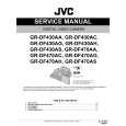
1. Loosen the three screws and open the outside panel. 2. Release the locks of CN501 and CN502 on the MB851 board and pull out the flexible card wires. (Refer to Section 1-7-3.)
CN501 CN502 Flexible card wires Screws

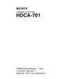
4. Remove the two slot-head screws and the two screws (M2 x 3) and remove 50-pin connector. n Do not lose the nuts on both sides of the 50-pin connector.
50-pin bracket

M2 x 3

Slot-head screws N2, TYPE2

50-pin connector N2, TYPE2

5. Desolder from the CN-1556 board and remove the 50pin connector. 6. Solder the new 50-pin connector on the CN-1556 board.
MB-851 board

50 spots
Outside panel Screw

50-pin connector

3. Remove the four screws and remove the 50 PIF assembly together with the flexible card wire from the unit.
M2.6 x 5 M2.6 x 5

CN-1556 board

50 PIF assembly

7. Install the 50 PIF assembly in the reverse order of steps 3 through 6. n When installing the 50 PIF assembly, pull the two flexible card wires toward the outside panel from the clearance between the unit and the MB-851 board. 8. Connect the two flexible card wires to CN501 and CN502 on the MB-851 board. (Refer to Section 1-7-3.) 1-7 (E)

HDCA-701 MM

Quizás también quiera comprar

$4.99

HDCA-701 SONY
Manual de Usuario

Manual del propietario completo en formato digital. El manual estará disponible para descarga como …
>
Parse Time: 0.181 - Number of Queries: 100 - Query Time: 0.04