|
|
|
Productos
|
|
Información
|
|
Destacado
|
|
|
No hay comentarios de productos.
HCD-CL1/CL3
Note : Clear RF signal waveform means that the shape � � � can be clearly distinguished at the center of the waveform.
Adjustment Location: [BD (CD) BOARD] (Conductor Side)
RF signal waveform VOLT/DIV : 200mV TIME/DIV : 500ns
level : 0.65 ±0.15Vp-p (RFDC) 1.1 ±0.4Vp-p (RFAC)
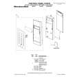
E-F Balance (1 Track jump) Check
BD (CD) board TP(TEO) TP(DVC) oscilloscope
TP (DVC) TP (RFAC) 15 1 IC103 16 30 TP (FEO) TP TP (TEO) (FEI)
21 20
40 41
IC101
1 80
Procedure : 1. Connect an oscilloscope to TP (TEO) and TP (DVC). 2. Turn Power switch on. 3. Load a disc (LUV-P01) and playback the number nine track. 4. Press the gG button. (Becomes the 1 track jump mode.) 5. Confirm that the level B and A (DC voltage) on the oscilloscope waveform.
1 track jump waveform center of waveform B A (DC voltage) DVC level=1.0 ±0.5Vp-p symmetry
TP (RFDC)
60 61
RV101
6. Adjust RV101 on the BD board so that the center of waveform becomes the same voltage of DVC. (i.e. A=0V)
20
|
|
 |
> |
|