|
No hay comentarios de productos.
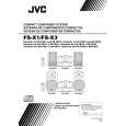
3.1.8 Removing the digital amplifier board (See Fig.11) � Prior to performing the following procedures, remove the rear cover, bottom case (A), bottom case (B) and top case assembly. (1) From the left side of the main body, disconnect the wire from the connector CN301 on the digital amplifier board. (2) Remove the spacer and tie band fixing the wire. (3) Remove the two screws K, two screws L and screw L' attaching the digital amplifier board. (4) Pull the digital amplifier board toward this side, disconnect the connectors CN961 and CN981 on the digital amplifier board. Reference : � When attaching the screw L', attach the earth wire together it. � After connecting the wire, fix the wire with the spacer and tie band.
Digital amplifier board
Tie band
K
CN981 CN961 Spacer
K
Wire
Earth Wire
CN301
L
L'
Fig.11
L
3.1.9 Removing the power supply board (See Figs.12 to 14) � Prior to performing the following procedures, remove the rear cover, bottom case (A), bottom case (B), top case assembly, tuner, function board, micon board and digital amplifier board. (1) From the top side of the main body, remove the two screws M attaching the center chassis. (See Fig.12.) (2) From the bottom side of the main body, remove the two screws N attaching the power supply board. (See Fig.13.) (3) Disconnect the card wire from the connector CN903 on the power supply board. (See Fig.14.) (4) Remove the three screws P attaching the power supply board. (See Fig.14.) (5) Remove the barrier (E) and barrier (F) under the power supply board. (See Fig.14.) Reference : � Before attaching the each parts, pass the card wire through the holes f on the center chassis. � After attaching the center chassis, put the earth wire through the slit g of the power supply board and sections h of the center chassis.
N
Power supply board
N
Fig.13
Bottom chassis
Card wire
Hole f
Center chassis
P
Power supply board Card wire
M M P
Bottom chassis Earth wire Slit g
Fig.12
Section h
Barrier (E) Barrier (F)
P
Fig.14
CN903
1-12 (No.MB004)
 $4.99 FS-X1 JVC
Manual de Usuario Manual del propietario completo en formato digital. El manual estará disponible para descarga como …
|