|
No hay comentarios de productos.
SECTION 3 DISASSEMBLY
3.1 Main body section 3.1.1 Removing the top cover (See Fig.1) (1) From the top side of the main body, remove the four screws A attaching the top cover.
A
Top cover
A
A
Fig.1 3.1.2 Removing the AL panel L and AL panel R (See Figs.2 to 7.) � Remove the top cover. (1) Remove the two screws B, screw C and screw C' attaching the bridge A. (See Fig.2.) Reference: When attaching the screw C' attach the lug wire with it. (See Fig.2.) (2) Remove the two screws C attaching the bridge B. (See Fig.2.) (3) Remove the screw C and screw C' attaching the bridge C. (See Fig.2.) Reference: When attaching the screw C' attach the lug wire with it. (See Fig.2.) From the back side of the main body, remove the three screws D attaching the bridge C. (See Fig.3.) From the top side of the main body, remove the two screws E attaching the AL panel L and AL panel R. (See Fig.4.) From the bottom side of the main body, remove the three screws F attaching the wood bar. (See Fig.5.) Remove the six screws G and two screws H attaching the AL panel L and AL panel R. (See Fig.6.) Remove the AL panel L and AL panel R in the direction of the arrow 2 while extending the back section of the AL panel L and AL panel R in the direction of the arrow 1. (See Fig.7.)
Bridge C Lug wire Bridge B
C'
C
C
C
(4) (5) (6) (7) (8)
C'
C
Bridge A
Fig.2
B
(No.MB150)1-7
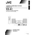 $4.99 EX-A1 JVC
Manual de Usuario Manual del propietario completo en formato digital. El manual estará disponible para descarga como …
|