|
|
|
Productos
|
|
Información
|
|
Destacado
|
|
|
No hay comentarios de productos.
5
6
7
8
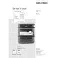
Check 5: Is the video circuit operated normally?
Reproduce DVD-REF-A1(GGV1018) Title 2 Chapters (White 100IRE). Monitor the output with the oscilloscope, by setting the COMPO signal to a GND reference. Set the Trigger mode to the TV trigger, and the Trigger line to line-150.
A
NO. 1
Verification location (sensing pin) COMPO
Rated value 1.0±0.02Vpp
Reference waveform Waveform 6
If the result is not satisfactory, check to see if there are any problems with resin flux cored solder, parts and components, in the vicinity of line-150 (the section marked 5 in the circuit diagram) and peripheral components
PEAK
COMPO signal
Rated value Color burst Pedestal BOTTOM Horizontal periodic signal
When the result is not satisfactory, adjust the noise level to 1.0 + 0.02 Vpp.
B
Composite signal 100% output waveform
C
D
DVH-P7000R
5 6 7 8
117
|
|
 |
> |
|