|
|
|
Productos
|
|
Información
|
|
Destacado
|
|
|
 |
|
|
No hay comentarios de productos.
1
2
3
4
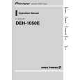
1.3 AUTOMATIC ADJUSTMENT FUNCTION
A
In this system, all the circuit adjustments are automated in the CD block of the LSI. All adjustments are performed whenever a disc is inserted or the CD mode is selected by pressing the source key. Details of each adjustment will be explained below.
1.3.1 TE, FE, and RF offset auto-adjustment
In this adjustment the TE, FE, and RF amplifier offsets of the preamplifier block in POWER ON are adjusted to the respective target values with the REFO as reference. (The target values for TE, FE, and RF offsets are 0V, 0V, and - 0.8 V, respectively.) Adjusting procedure 1) The CPU unit of the LSI respective offsets through the CD block of the LSI, when they are in LDOFF status. 2) The CPU unit of the LSI calculates the voltages for correction from the values read in 1), and substitutes the corrected values to prescribed places to adjust.
B
1.3.2 Tracking balance (T.BAL) auto-adjustment
This adjustment is to equalize the pickup output offsets for E-ch and F-ch by changing the amplifier gain in the CD block of the LSI. In actual operation, adjustment is performed so that the TE waveform becomes symmetrical on each side of the REFO. Adjusting procedure 1) After closing the focus loop, 2) Kick the lens in the radial direction to ensure the generation of the TE waveform. 3) The CPU unit of the LSI reads the TE offset calculated in the LSI through the CD block of the LSI. 4) The CPU unit of the LSI determines the offset amount is 0, positive, or negative. - When the offset amount is 0, the adjustment is completed. - When the offset amount is positive or negative, the amp gains for E-ch and F-ch should be changed, following a certain rule. Then, steps 2) to 4) are repeated until the offset amount becomes 0 or the repetition reaches the limit number of times.
C
1.3.3 FE bias auto-adjustment
D
This adjustment is to maximizes the RFO level by optimizing the focus point during the play mode, utilizing the phase difference between the 3T level waveform of the RF waveform and that of when focus error disturbance is input. This adjustment is performed at the same timing as the auto-gain control, which will be described later, since disturbance is input to the focus loop. Adjusting procedure 1) The CPU unit of the LSI issues the command to introduce disturbance to the focus loop (CD block of the servo LSI). 2) The waver of the 3T component of the RF signal is detected in the CD block of the LSI. 3) The relation between the 3T component above and the disturbance is processed in the CD block of the LSI to detect the volume and direction of the focus offset. 4) The CPU unit of the LSI issues a command and reads out the detected results from the CD block of the LSI. 5) The CPU unit of the LSI calculates the necessary correction and substitutes the result to the bias adjustment term inside the CD block of the LSI. Additionally, in this adjusting, a series of steps are repeated for better adjustment accuracy, the same as in the auto-gain control.
E
F
14
CX-3166
1 2 3 4
|
|
|
> |
|