|
No hay comentarios de productos.
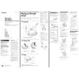
SECTION 3 DISASSEMBLY
Note : Follow the disassembly procedure in the numerical order given.
3-1. CABINET (LOWER) SUB ASSY
Note : When installing, fit the knobs (H-B) and switches.
4 claw (Open the battery case Lid.) 3 claw 1 screws (B2x10) (G), tapping
2 screws (B2x10) (G), tapping 7 cabinet (lower) sub assy
knob (H-B) 6 claw knob (H-B)
5 claw
switches
3-2. MAIN BOARD
3-3. MD ASSY
1 MD assy 4 MAIN board
1 CN501
2 CN502 3 CN503
�6�
|