|
No hay comentarios de productos.
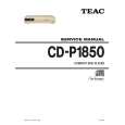
SCHEMATIC DIAGRAM
1 2
CD-P1850
POWER PCB
3 4 5
SW201 SW-POWER LIVE POWERCORD EC202 EC-TERMINAL C201
100V
T201
J201 13 12
1 3
0.01uF NEUTRAL EC201 EC-TERMINAL 4L50005800
0V
A
11 9 7
J202
CN201
1 2 3 4 5
CONNECTOR 5P ASSY
1 2 3 4 5
5
TO PCB MAIN CN105
POWER PCB
B
C
1. Resistor values are in ohms (k=kilo-ohms, M=megohms). 2. Capacitor values are in microfarads (p=picofarads). 3. £Parts marked with this sign are safety critical components. They must always be replaced with identical components-refer to the appropriate parts list and ensure exact replacement.
NOTES:
1. æ�µæ��ã�®å��ä½�ã�¯Î© ï¼�ï½�ï¼�ï½�Ωï¼�ï¼ï¼�ï¼Î©ï¼� ã�§ã��ã�� 2. ã�³ã�³ã��ã�³ã�µã�®å��ä½�ã�¯Î¼ï¼¦ ï¼�ï½�ï¼�ï½�Fï¼� ã�§ã��ã�� 3. £ã��ã�¼ã�¯ã�®ã��ã��é�¨å��ã�¯å®�å�¨è¦�æ ¼é��è¦�é�¨å��ã�§ã��ã�� 交æ��ã��ã��ã�¨ã��ã�¯å¿�ã��ã��ã�£ã�¢ã��ã�¯æ��å®�ã�®é�¨å��ã��使ç�¨ã��ã�¦ã��ã� ã��ã��ã��
注�
CD-P1850
COMPACT DISC PLAYER
1 st Issue; March 2001
|