|
|
|
Productos
|
|
Información
|
|
Destacado
|
|
|
 |
|
|
No hay comentarios de productos.
1
2
3
4
Display (2/2)
Sites
A
Waveforms
Points to be checked
Causes & Measures to be taken
Remarks
No indication only on the JOG-FL display If the power supply is normal, this symptom can be caused only by a failure in the JOG-FL (V601) or the communication between the JOG-FL and the DISPLAY MPU (IC501). z Enter Display Check mode of Service mode and check if other keys on the control panel function and if the LEDs light. If the LEDs and DATA-FL (V501) do not light, nor does the JOG-FL (V601) display, the DISPLAY MPU that controls those will not function properly. See "Lighting of the LEDs and indications and the FL display on the control panel do not function." Set the switch to the position that corresponds to the commercial power source.
ACIN Assy JFLB Assy DFLB Assy SECB Assy TRNS Assy JFLB Assy
x Check the setting of the voltage selector switch (on the rear panel). (for RLF model)
B
c Check the Vload voltage (VLD, VLDD, VLDJ). If the voltage is 0 V, the ICPs (IC25, IC58, IC59, If the voltage measured at the periphery of the and IC603) are fried. Replace the ICPs. power terminal of the JOG-FL (V601) is 27.8 V DC or more, it is OK. v Check the FLAC voltage (FLAC3, FLAC4). If the voltage measured at the both ends of the JOG-FL (V601) lead is 2.6 V AC or more, it is OK. If the AC current waveform does not appear, check the connection between the Assys.
JFLB Assy
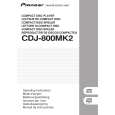
b Check the waveform at Pin 23 of JOG-FL If the 5 V power is not supplied, soldering (V601), to confirm that 5 V power is supplied to the touchup is needed. built-in driver. JFLB Assy 60 to 63 n Check the points designated in the waveform photo to confirm that the procedures of the communication between the DISPLAY MPU (IC501) and the JOG-FL (V601) are normal. A solder fracture of the JOG-FL terminal or loose connection of the terminals on the communication line between the DISPLAY MPU and the JOG-FL is suspected. Soldering touchup is needed. If the symptom is not ameliorated after soldering touchup, replace the JOG-FL.
JFLB Assy
C
No indication on either the DATA-FL nor JOG-FL displays This symptom occurs when the Vload voltage, to be supplied to both the DATA-FL (V501) and JOG-FL (V601), is not supplied. JFLB Assy DFLB Assy SECB Assy z Check if the Vload voltage (VLD, VLDD, VLDJ) is supplied. x Check if the Vload power circuit is reset canceled. Check if the voltage at Pin 9 of CN56 becomes high after the power is turned on. If the voltage is 0 V, the ICPs on the line are fried. Replace the ICPs. Resetting of this circuit is performed by the Reset circuit (IC502) mounted on the DLFB Assy. Resetting is done simultaneously with the DISPLAY MPU (IC501). As only the FL display has a problem, Pin 9 of CN501 on the DFLB Assy is in failure.
Part of the FL display does not light, frequently flickers, or is dark.
D
DFLB Assy JFLB Assy JFLB Assy DFLB Assy SECB Assy TRNS Assy
z Visually check if the symptom occurs constantly in the same area.
If the symptom occurs constantly in the same area, the FL display is defective.
x If the symptom does not occur in the same If the supply is unstable, soldering touchup is area, check the waveform of the Vload voltage, needed. If the symptom persists, replace the FLAC voltage and 5 V power, to confirm that the part. supply is stable. (See Steps c, b, and n in "No indication only on the DATA (or JOG)-FL display.")
Black dots or stains appear on some parts of the FL display afer Display Check mode of Service mode is entered. Impurities in the FL tube are the cause. For amelioration, replace the DATA-FL or JOGFL.
E
F
96
1 2
CDJ-800MK2
3 4
|
|
|
> |
|