|
|
|
Productos
|
|
Información
|
|
Destacado
|
|
|
 |
|
|
No hay comentarios de productos.
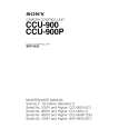
Location and Function of Parts
Front Panel
1 Red tally lamp 2 Green tally lamp 3 MIC switch 4 INTERCOM control
8 INTERCOM connector 7 CAMERA POWER switch and indicator 6 MAIN POWER switch and indicator 5 CABLE ALARM indicator
1 Red tally lamp Lights when a red tally signal is received. When the CALL button on the video camera, Master Setup Unit MSU-700A/750, RCP-700-series Remote Control Panel, etc. is pressed, this lamp will go out if previously lit, and light up if previously off. A supplied number plate can be mounted here. 2 Green tally lamp Lights when a green tally signal is received. A supplied number plate can be mounted here. 3 MIC (microphone selection) switch Used to select the type of headset microphone being used, or to turn microphone input off. DYNAMIC: for a dynamic microphone OFF: turns microphone input off CARBON: for a carbon microphone 4 INTERCOM (intercom volume adjustment) control Adjusts the intercom input level. 5 CABLE ALARM indicator SHORT: This indicator lights when there is a short circuit between a power supply line and the sheath of the optical-fiber cable, or when the two powersupply lines are shorted. When this indicator lights, the power supply is shut off. (If the
optical-fiber cable is long, this indicator may light for a few seconds after the main power is turned on until the short-circuit detection circuitry begins operating normally. This is not a malfunction.) OPEN: Lights when there is no camera connected via an optical-fiber cable to the CAMERA connector on the rear panel. The indicator blinks slowly when reception of light is in WARNING status, and blinks fast when it is in CARE status. 6 MAIN POWER switch and indicator Turns on/off the power to the entire system, consisting of the CCU-900/900P, a video camera, an RCP-700series Remote Control Panel connected via the REMOTE connector, etc. Setting the switch to the ? position turns the power on, and setting it to a turns it off. The indicator is lit when the power supply is on. 7 CAMERA POWER switch and indicator Turns on/off the power to the camera when the MAIN POWER switch is on. Setting the switch to the ? position turns the power on, and setting it to a turns it off. When a remote control panel is connected and the power supply is turned off with the CAM PW button on the remote control panel, this switch alone cannot be used to turn on the power of the video camera.
8
|
|
|
> |
|