|
|
|
Productos
|
|
Información
|
|
Destacado
|
|
|
 |
|
|
No hay comentarios de productos.
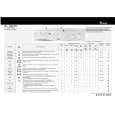
1-3. Name and Function of Switch/Indicator Switch/Indicator/etc.
1-3. Name and Function of Switch/Indicator/etc.
1 2 3 5 7 9 !0
ON
!=
VIDEO SYNG NORMAL SWAP
![ !] !\
WORD
!;
D808 D807 D809
4 6 8
ON ON
S401 RV405 S402 RV406 S403 RV407 S404 RV408
S705
S5
S1 S3 S4
NTSC PAL HD OFF ON
NORMAL HIGH
ON
Main Board (ADC-40 Board: Side A)
Switches/gain adjusting VRs (Factory default settings are indicated by a \ mark)
No. Ref. No. !] S1 Name Function
WORD SYNC SELECT Selects the output level of the regenerated-word-clock signal output to the REF VIDEO/ WORD CLOCK (OUT) connector. \ NORMAL: 1 V p-p HIGH: 2.8 V p-p (using the traditional digital audio models) 75 Z 75 Z termination ON/OFF switch for the REF VIDEO/WORD CLOCK IN connector. \ OFF: When using the loop-through connection ON: Otherwise Selects the signal method of the video reference input signal. (Valid only when S5 is set to VIDEO.) \ NTSC PAL: NTSC or PAL method HD: HD method Selects the reference signal input to the REF VIDEO/WORD CLOCK IN connector. \ VIDEO: Input the video reference (NTSC, PAL, or HD) signal WORD SYNC: Input the word-clock signal Selects each input impedance of the audio signals input to the AUDIO IN connectors. \ ON: 600 Z OFF: 20 k Z Switch the channel output to each connector of the AES/BEU OUT. \ NORMAL: CH1/2 8 No. 1, CH3/4 8 No. 2 SWAP: CH3/4 8 No. 1, CH1/2 8 No. 2 Adjusts the audio input level of the each channel within the range between _4 dB (+8 dBm input) and +14 dB (_10 dBm input). (At the factory-out, they were adjusted so as to convert an analog audio signal +4 dBm into a digital audio signal _20 dB FS.)
!; S3
!\ S4
VIDEO SELECT