|
|
|
Productos
|
|
Información
|
|
Destacado
|
|
|
 |
|
|
No hay comentarios de productos.
2-1. Electrical Alignment Overview 2-2. Preparation for Adjustment 2-3. Free-running Frequency Adjustment
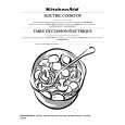
2-1-3. Initial Setting of Switches/Variable Resistors
ADC-35 Board
RV401 RV404 TP411 RV402 RV407 S601 RV408 TP412 COR402 COR401 S602 S504 E5 S401 RV406 TP403 RV405 S500 TP402 RV400 RV102 RV203 RV303 RV403 RV501
2-2. Preparation for Adjustment
1. Connect the equipment and tools. (Refer to Section 21-2.) 2. Set the switches on the ADC-35 board. (Refer to Section 2-1-3.) 3. Turn on the power of the digital interface unit (PFVD20/D50/D100A/D200A/D300) and warm up the unit for about 10 minutes.
2-3. Free-running Frequency Adjustment
Measurement equipment Oscilloscope Frequency counter Procedure 1. Supply 100% color bars signal from the signal generator to the ANALOG IN connectors. 2. Set the oscilloscope as follows. CH2 : 0.5 V/DIV AC TIME : 20 ns/DIV TRIG : CH2 (TP403) 3. Connect the CH2 probe of the oscilloscope to TP403. Connect the GND probe to E5. 4. Turn 1RV406 clockwise until the frequency level satisfies the specification. 5. After the adjustment is completed, set S401 to OFF. Measuring point : TP403 (J-6)/ADC-35 Adjustment point : 1RV406 (H-6)/ADC-35 Specification : 26.9 ±0.1 MHz
Component side (A side)
n 1RV203 (F-2) and 1RV303 (F-3) are used for factory setting. Do not change the settings. Set the switches before the adjustment as below.
Ref. No. (Address) S401 (G-6) S500 (H-5) S504 (A-6) S601 (A-4) S602 (A-5) 1RV406 (H-6) 1RV501 (H-4) Initial Setting ON H INT CCIR YUV Counterclockwise Mechanical center
2-2 (E)
BKPF-101CB
|
|
|
> |
|