|
|
|
Productos
|
|
Información
|
|
Destacado
|
|
|
 |
|
|
No hay comentarios de productos.
2-10. DP & DG Check 2-11. SCH Adjustment
2-10. DP & DG* Check
Measurement equipment Waveform/vector monitor Procedure 1. Supply a ramp signal (with chroma) from the signal generator (TSG-170A) to the ANALOG IN connector. 2. Set the waveform/vector monitor as follows. MODE : VECTOR DP & DG measuring INPUT : CH A n To change to the DP & DG measuring display, push the measure button and touch DP & DG item on the display (the display is a touch panel). Measuring point : ANALOG OUT connectors (BKPF-102 connector panel)
2-11. SCH Adjustment
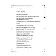
Measurement equipment Oscilloscope Procedure 1. Supply 75% (SMPTE) color bars signal from the signal generator (TSG-170A) to the ANALOG IN connector. 2. Set the oscilloscope as follows. CH2 : 2 V/DIV AC TIME : 50 ns/DIV TRIG : CH1 (ANALOG OUT) or CH4 (EQ OUT) Measuring point : TP102 (E-4)/AD-147 Adjustment point : 1RV3 (E-4)/AD-147
A
DP DP < 1% TP102
50%
DG DG < 1%
A = 70 ±5 ns
*DP : Differential Phase
DG : Differential Gain 2-6 (E)
BKPF-101A
|
|
|
> |
|