Su carrito de compras está vacío
 
English Polski Spanish 
Buscar un manual
 

(p.Ej. AA-V20EG JVC, ZX-7 Sony)
PayPal 1000+ rating Secure, Encrypted Checkout.
 
Usuarios conectados
Actualmente hay 5643 visitantes y 
2 usuarios online.
Productos
Información
Destacado
Inicio >> TOSHIBA >> 15VL26P Manual de Servicio
 
 0 artículo(s) en Su carrito 

TOSHIBA 15VL26P
Manual de Servicio


¡Twitee acerca de este producto y obtenga $1.00 de crédito en la tienda para uso!
  • Contiene diagramas del circuito
  • Descargable
  • Formato PDF
  • Manual completo
  • Idiomas: English
Precio: $4.99

Descripción del TOSHIBA 15VL26P Manual de Servicio

Manual de servicio completo en formato digital (archivo PDF). Los manuales de servicio por lo general contienen diagramas de circuitos, tarjetas de circuitos impresos, consejos para reparación, diagramas de cableado, diagramas de bloque y lista de refacciones. El Manual de Servicio (a veces llamado Manual de Reparación) es usado principalmente por los técnicos.

Si tan solo quiere saber cómo utilizar su televisión, reproductor de vídeo, reproductor de mp3, etc. Quizá lo que necesita es el Manual del Propietario. Después de colocar la orden le enviaremos las instrucciones de descarga a su dirección de e-mail.

The manual is available in languages: English

Not yet ready
You must purchase it first

Opiniones de los clientes
No hay comentarios de productos.

TEXT_PDF_SNIPPET
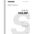
2-4. Sensor PC Board
1. Remove one screw (1) and remove the connector (2) from the one location, then remove the sensor PC board (3).
Screw (1)

2-5. LCD Rear Cover
1. Remove the front panel, the LCD panel and the inverter PC board. (Refer to item 1-1, 1-2 and 1-3.) 2. Remove two screws (1), then remove the support (2). 3. Remove two screws (3) and remove the LCD rear cover (4) in a vertical position. Note:
Connector (2)

� If not removed when in a vertical position, the hinges may become deformed.

Sensor PC board (3)

LCD rear cover (4)

Screws (3)

Fig. 1-2-9

Note: � When attaching the sensor PC board (3), bundle the wires with the band (4) and insert into groove then attach the sensor PC board (3) from the top.
Sensor PC board (3) Band (4) Wires

Support (2) Screws (1)

Guide

Fig. 1-2-11

Place the bundled wires (4) into this groove and attach the sensor PC board (3) on the top.

Fig. 1-2-10

1-6

Quizás también quiera comprar

$4.99

15VL26P TOSHIBA
Diagrama del circuito

Conjunto de diagramas del circuito. Los diagramas serán proporcionados en un archivo PDF. El archiv…

$4.99

15VL26P TOSHIBA
Manual de Usuario

Manual del propietario completo en formato digital. El manual estará disponible para descarga como …
>
Parse Time: 0.65 - Number of Queries: 105 - Query Time: 0.304