|
No hay comentarios de productos.
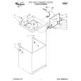
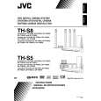
3.1.8 Removing the power board (See Figs.10 and 11) � Prior to performing the following procedures, remove the top cover assembly or metal cover. (1) From the back side of the main body, remove the screw M attaching the power board to the rear panel. (See Fig.10) (2) From the top side of the main body, disconnect the parallel wires from the connectors (CN404 to CN407) on the main board. (See Fig.11) (3) Remove the three screws N attaching the power board. (See Fig.11) (4) Take out the power board from the main body. Reference: When attaching the power board on the chassis base, align the projection d of the chassis base in the hole of the power board. (See Fig.11.)
Rear panel
M
Fig.10
N
CN407 CN406 Main board
d
CN404
CN405
N
Fig.11
Power board
3.1.9 Removing the main board (See Figs.12 and 13) � Prior to performing the following procedures, remove the top cover assembly or metal cover, audio signal I/O board and tuner. (1) From the back side of the main body, remove the seven screws P attaching the rear panel. (See Fig.12.) (2) Release the engagement sections e and remove the rear panel from the main body. (See Fig.12.) (3) From the top side of the main body, disconnect the card wires from the connectors (CN401 to CN403, CN408, CN409, CN451, CN452) on the main board. (See Fig.13.) (4) Disconnect the parallel wires from the connectors CN404 to CN407 on the main board. (See Fig.13.) (5) Remove the spacers fixing the card wires on the main board. [For XV-THS9, XV-THS7 models] (See Fig.13.) Reference: After attaching the main board, fix the card wire with the spacers as before. (6) Remove the three screws Q attaching the main board on the main body. (7) Take out the main board from the main body.
Rear panel
e
e
P
Fig.12
CN406
P
CN407 Spacer
P
Spacer CN408
P
CN405 CN404
CN452
CN401 CN403 CN409 CN402 CN451
Main board
Fig.13 1-12 (No.MB236)
|