|
No hay comentarios de productos.
XM-280GTX SECTION 3 DIAGRAMS
2-4. MAIN BOARD
THIS NOTE IS COMMON FOR PRINTED WIRING BOARDS AND SCHEMATIC DIAGRAMS. (In addition to this, the necessary note is printed in each block.) for schematic diagram: Note: � All capacitors are in µF unless otherwise noted. pF: µµF 50 WV or less are not indicated except for electrolytics and tantalums. � All resistors are in � and 1/4 W or less unless otherwise � � � � � � � specified. % : indicates tolerance. 2 : nonflammable resistor. A : B+ Line. B : B� Line. Power voltage is dc 14.4V and fed with regulated dc power supply from +12V and REM terminals. Voltage is dc with respect to ground under no-signal condition. Voltages are taken with a VOM (Input impedance 10 M�). Voltage variations may be noted due to normal production tolerances. Waveforms are taken with a oscilloscope. Voltage variations may be noted due to normal production tolerances.
3 P 3x8
�
5 MAIN board 2 P 3x8
� Circled numbers refer to waveforms. � Signal path. F : AUDIO
1 P 3x8 4 panel (front)
for printed wiring boards: Note: � X : parts extracted from the component side. � : Pattern from the side which enables seeing. (The other layer�s patterns are not indicated.) Caution: Pattern face side: Parts on the pattern face side seen from the (Side B) pattern face are indicated. Parts face side: Parts on the parts face side seen from the (Side A) parts face are indicated.
2-5. LED BOARD
1 P 3x6
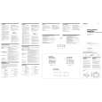
3-1. IC BLOCK DIAGRAM
2 LED board
IC8 TL494CN
OUT VCC C2
11 16 15 14 13 12 REF 5V 10
E2
9 6 78
heat sink (main)
ERROR
ERROR 1 2 3
0.1V
OSC
4
5
-IN INV
TIME
� Waveform
1
1V/DIV, 5µsec/DIV 3.4Vp-p 15µsec
COMP EN VREF
IC8
5
9
9
GND C1 E1
+IN NON
RT
CT
|