Su carrito de compras está vacío
 
English Polski Spanish 
Buscar un manual
 

(p.Ej. AA-V20EG JVC, ZX-7 Sony)
PayPal 1000+ rating Secure, Encrypted Checkout.
 
Usuarios conectados
Actualmente hay 5987 visitantes online.
Productos
Información
Destacado
Inicio >> JVC >> XLR910SL Manual de Servicio
 
 0 artículo(s) en Su carrito 

JVC XLR910SL
Manual de Servicio


¡Twitee acerca de este producto y obtenga $1.00 de crédito en la tienda para uso!
  • Contiene diagramas del circuito
  • Descargable
  • Formato PDF
  • Manual completo
  • Idiomas: English
Precio: $4.99

Descripción del JVC XLR910SL Manual de Servicio

Manual de servicio completo en formato digital (archivo PDF). Los manuales de servicio por lo general contienen diagramas de circuitos, tarjetas de circuitos impresos, consejos para reparación, diagramas de cableado, diagramas de bloque y lista de refacciones. El Manual de Servicio (a veces llamado Manual de Reparación) es usado principalmente por los técnicos.

Si tan solo quiere saber cómo utilizar su televisión, reproductor de vídeo, reproductor de mp3, etc. Quizá lo que necesita es el Manual del Propietario. Después de colocar la orden le enviaremos las instrucciones de descarga a su dirección de e-mail.

The manual is available in languages:

Not yet ready
You must purchase it first

Opiniones de los clientes
No hay comentarios de productos.

TEXT_PDF_SNIPPET
XL-R910SL

Disassembly method
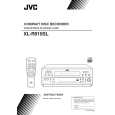
<Main body> Removing the metal cover (See Fig.1)
1.Remove the three screws A attaching the metal cover on the back of the body. 2.Remove the four screws B attaching the metal cover on both sides of the body. 3.Remove the metal cover from the body by lifting the rear part of the cover. ATTENTION : Do not break the front panel tab fitted to the metal cover. Bx2 A Bx2 Fig. 1 A A Metal cover

Removing the front panel assembly (See Fig.2~5)
* Prior to performing the following procedure, remove the metal cover. 1.Remove the three screws C attaching the front panel assembly on the bottom of the body and both sides of the body. 2.Disconnect the card wire from connector CN601 on the servo control board. 3.Disconnect the 4pin wire from connector CN502 on the servo control board. 4.Disconnect the 3pin wire and 8pin wire from connector ACW1 and RCW2 on the main board. Please remove a tie band if necessary. Please fix the wire again with a tie band when assembling. 5.Release the two joints a on the lower part of the sides using a screwdriver, and remove the front panel assembly toward the front.

Front panel assembly

C

Fig. 2

Front panel assembly

joint a Fig. 3 C

RCW2 ACW1

F
RCW1 Main board

Front panel assembly

F
Tie band Mechanism assembly

G
NCW1 CN502 Tie band CN701 CN601

D

Joint a

C

Fig. 4

Fig. 5

1-3

Quizás también quiera comprar

$4.99

XLR910SL JVC
Manual de Usuario

Manual del propietario completo en formato digital. El manual estará disponible para descarga como …
>
Parse Time: 0.232 - Number of Queries: 100 - Query Time: 0.063