|
|
|
Productos
|
|
Información
|
|
Destacado
|
|
|
 |
|
|
No hay comentarios de productos.
ELECTRICAL ADJUSTMENTS
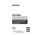
2-5: STEREO SEPARATION NOTE: Adjust after performing adjustments in section 2-4. 1. Receive the stereo signal. (L=2KHz, R=400Hz) 2. Connect the AC voltmeter to AUDIO OUT L/R through stereo filter (L=400Hz, R=2KHz). 3. Check if the difference between with the stereo filter and without the stereo filter is more than 23dB. 2-9: HORIZONTAL SIZE NOTE: Adjust after performing adjustments in section 2-8. Measurement Equipment Maker: SHIBASOKU Co. Limited Measurement Equipment Model No.: DIGITAL TEST PATTERN GENERATOR 588 1. Receive the monoscope pattern. 2. Adjust the VR401 until the SHIFT quantity of the OVER SCAN on right and left becomes 10 ± 2%. (Simple Adjustments) 1. Activate the adjustment mode display of Fig. 1-1 and press the channel button (6) on the remote control. The Fig. 2-5 appears on the display. 2. Press the channel button (6) on the remote control. 3. Adjust the VR401 until the right vertical line of the pattern becomes fit to the right end. 1. EXTERNAL 2. BLACK 3. WHITE (100) 4. WHITE (60) 5. CROSS (100) 6. CROSS (60) 7. 8.
(TV SECTION)
2-6: CONSTANT VOLTAGE 1. Connect the digital voltmeter to TP501. 2. Set condition is AV MODE without signal. 3. Adjust the VR502 until the DC voltage is 111 ± 0.5V. 2-7: OSD HORIZONTAL 1. Using the remote control, set the brightness and contrast to normal position. 2. Activate the adjustment mode display of Fig. 1-1 and press the channel button (5) on the remote control. The Fig. 2-2 appears on the display. 3. Press the channel button (4) on the remote control. 4. Press the VOL. UP/DOWN button on the remote control until the difference of A and B becomes minimum. (Refer to Fig. 2-3) [ TV ]
0. RETURN
"The adjustment items 1, 2, 3, 4 and 5 are not used for this model." Fig. 2-5 2-10: VERTICAL SIZE NOTE: Adjust after performing adjustments in section 2-9.
OSD H
1. Receive the cross hatch signal from the Pattern Generator. 2. Using the remote control, set the brightness and contrast to normal position. 3. Activate the adjustment mode display of Fig. 1-1 and press the channel button (1) on the remote control. The Fig. 2-4 appears on the display. 4. Press the channel button (3) on the remote control. 5. Press the VOL. UP/DOWN button on the remote control until the rectangle on the center of the screen becomes square. 6. Receive a broadcast and check if the picture is normal. 2-11: VERTICAL LINEARITY NOTE: Adjust after performing adjustments in section 2-10. 1. Receive the cross hatch signal from the Pattern Generator. 2. Using the remote control, set the brightness and contrast to normal position. 3. Activate the adjustment mode display of Fig. 1-1 and press the channel button (1) on the remote control. The Fig. 2-4 appears on the display. 4. Press the channel button (5) on the remote control. 5. Press the VOL. UP/DOWN button on the remote control until the SHIFT quantity of the OVER SCAN on upside and downside becomes minimum. 0. RETURN
A 2-8: HORIZONTAL PHASE
B
Fig. 2-3
1. Receive the center cross signal from the Pattern Generator. 2. Using the remote control, set the brightness and contrast to normal position. 3. Activate the adjustment mode display of Fig. 1-1 and press the channel button (1) on the remote control. The Fig. 2-4 appears on the display. 4. Press the channel button (1) on the remote control. 5. Press the VOL. UP/DOWN button on the remote control until the right and left screen size of the vertical line becomes the same. 1. H. PHASE 2. H. BLK 3. V. SIZE 4. V. POSI 5. V. LIN 6. V. SC 7. V. COMP 8. (H FREQ)
"The adjustment item 8 is not used for this model." Fig. 2-4
D2-2
|
|
|
> |
|