|
|
|
Productos
|
|
Información
|
|
Destacado
|
|
|
 |
|
|
No hay comentarios de productos.
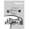
Wiring Diagram page 1/4
Do the styling so that the binding tape of �ELCD3� should not pass the upper the frame. (Prevent it from touching with the back-cover.) �ECN" must pass on �ELCD3�. *Refer to detail 1 (page2/4)
D8MW
1) Do the styling so that the wire should not touch the T-CON shielding case. 2) Do the styling so that the wire should not on the swell of the frame.
Frame
T-COM PWB
ELCD2
Insert it surely.
ELCD3 EPS
14pin
NSPK/NSPK2/NELS: MAG K5CRC12X15X7-MB2(p#GX00738) N001: MAG-FSRC400120RTF10T(p#GX00771)
#334 ECN Detail-1(page2/4)
#360 Detail-6(page4/4)
Detail-5(page3/4) #360
Do the styling so that the �EISP� wire should not touch the edge of the Inverter cover.
NSPK2
Detail-2(page2/4) EFFC #330 NELS
NSPK EISP EPU #NSPK #332
Do the styling so that the �EISP� wire should not touch the edge of the Inverter cover.
1) Take loosening of the �EISP� wire so that it is not pinched between the AC-switch. 2) Take loosening of the wire by putting in the ditch of the panel, and pulling it in the direction of the arrow.
ELS Detail-7(page4/4)
EKL
Set the ferrite core(NSPK) in EISP. 1turn. Fasten with the SK-binder(#NSPK) near NSPK.
Detail-3(page3/4)
Set the ferrite core(NELS) in ELS. 1turn. Pass the terminal board under.
Detail-4(page3/4)
TABLE OF CONTENTS
35
|
|
|
> |
|