|
No hay comentarios de productos.
SRF-HM03V SECTION 2 DISASSEMBLY
� This set can be disassembled in the order shown below.
2-1.
DISASSEMBLY FLOW
SET
2-2. POWER BOARD (Page 4)
2-4. MICON BOARD, MAIN BOARD (Page 5)
2-3. CABLE SETTING (Page 5)
2-5. PUTTING THE SHEET (A) (Page 6)
Note: Follow the disassembly procedure in the numerical order given.
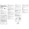
2-2.
POWER BOARD
8 Remove the eleven solders. green black red blue blue natural
gray black white red POWER board
1 six screws (1.7) 4 three screws (B1.4)
yerrow
knob
S401
6 screw (B1.4) 2
0 POWER board 9 screw (B1.4)
3 two screws (1.7) 7 lid (PWB BATT)
Note: When installing the POWER board, fit the knob and switch (S401).
5 cabinet assy front (L)
4
|