|
|
|
Productos
|
|
Información
|
|
Destacado
|
|
|
 |
|
|
No hay comentarios de productos.
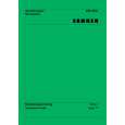
GUIDE UP/DOWN
GEAR LOADING
(L3)
(L6)
GEAR PULLEY (L6)
(L4)
BASE MAIN BELT LOADING PWB ASSEMBLY LOADING (H1)
(L6)
(S5)
BASE MAIN
(A) (A) (B) (L5) FIG. (A) (C) (B) GUIDE UP/DOWN GUIDE UP/DOWN (A) (B) (S4) FRAME ASSEMBLY UP/DOWN
GUIDE UP/DOWN
FIG. (B)
FIG. (C)
Fig. 4-4
5. Frame Assembly Up/Down
Note Put the Base Main face down(Bottom Side) 1) Release the Screw(S4) 2) Unlock the Locking Tab(L3) in direction of arrow and then lift up the Frame Assembly Up/Down to separate it from the Base Main. Note � When reassembling move the Guide Up/Down in direction of arrow(C) until it is positioned as Fig.(C). � When reassembling insert (A) portion of the Frame Assembly Up/Down in the (B) portion of the Guide Up/Down as Fig.(B)
8. Gear Loading (Fig. 4-4) 9. Guide Up/Down (Fig. 4-4)
1) Move the Guide Up/Down in direction of arrow(A) as Fig.(A) 2) Push the Locking Tab(L5) down and then lift up the Guide Up/Down to separate it from the Base Main. Note When reassembling place the Guide Up/Down as Fig.(C) and move it in direction arrow(B) until it is locked by the Locking Tab(L5). And confirm the Guide Up/Down as Fig.(A)
10. PWB Assembly Loading
Note Put the Base Main face down(Bottom Side) 1) Release 2 Screws(S5) 2) Unkool the Loading Motor Connector (C2) from the Hook (H1) on the Base Main. 3) Unlock 2 Locking Tabs(L6) and separate the PWB Assembly Loading from the Base Main.
6. Belt Loading(Fig. 4-4)
Note Put the Base Assembly Main on original position(Top Side)
7. Gear pulley (Fig. 4-4)
1) Unlock the Locking Tab(L4) in direction of arrow(B) and then separate the Gear Pulley from the Base Main.
11. Base Main(Fig. 4-4)
- 2-72 -
|
|
|
> |
|