|
|
|
Productos
|
|
Información
|
|
Destacado
|
|
|
No hay comentarios de productos.
1
2
3
4
RFD-1
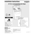
4. PCB CONNECTION DIAGRAM
4.1 DEM ASSY
A
KUC type : HOUSING ASSY(VKP2182) SD type : VOLTAGE SELECTOR
A DEM ASSY
B CN11
B
C CN3
POWER TRANSFORMER
NOTE FOR PCB DIAGRAMS:
1. Part numbers in PCB diagrams match those in the schematic diagrams. 2. A comparison between the main parts of PCB and schematic diagrams is shown below.
Symbol in PCB Diagrams Symbol in Schematic Diagrams Part Name
B BCE
C
EB
C
E Transistor
C
BCE
B
C
EB
C
E Transistor with resistor
D DGS
G
SD
G
S Field effect transistor
Resistor array
3-terminal regulator 3. The parts mounted on this PCB include all necessary parts for several destination. For further information for respective destinations, be sure to check with the schematic diagram. 4. Viewpoint of PCB diagrams
(VNP1649-A) Q5 Q4 Q1 Q2 IC201 IC200 IC5 IC3 IC9 IC7 Q3 Q6 IC1 IC2 IC6 IC8 IC4
Connector
Capacitor Chip Part
D
SIDE A
P.C.Board
SIDE B
SIDE A
8
A
1 2 3 4
|
|
 |
> |
|