|
|
|
Productos
|
|
Información
|
|
Destacado
|
|
|
 |
|
|
No hay comentarios de productos.
R-90GCH
MAGNETRON TEMPERATURE FUSE TF
The temperature fuse located on the waveguide flange is designed to prevent damage to the magnetron if an over heated condition develops in the magnetron due to cooling fan failure, obstructed air guide, dirty or blocked air intake, etc. Under normal operation, the temperature fuse remains closed. However, when abnormally high temperatures are reached within the magnetron, the temperature fuse will open at 150�C causing the oven to shut down.
FAN MOTOR (HIGH VOLTAGE TRANSFORMER SIDE) FM
The fan motor drives a blade which draws external cool air. This cool air is directed through the air vents surrounding the power transformer and cools the power transformer. This air is channelled through the oven cavity to remove steam and vapors given off from the heating foods. It is then exhausted through the exhausting air vents at the oven cavity.
TOP HEATER THERMAL CUT-OUT TC1
The thermal cut-out located on the thermal cover upper is designed to prevent damage to the top heating element unit if an over heated condition develops in the top heating element unit due to convection fan failure, thermistor failure, obstructed air ducts, dirty or blocked air intake, etc. Under normal operation, the thermal cut-out remains closed. However, when abnormally high temperature are reached within the top heating element unit, the thermal cut-out will open at 170�C causing the oven to shut down. When the thermal cut-out has cooled, the thermal cut-out closes at 155�C.
CONVECTION COOKING SYSTEM
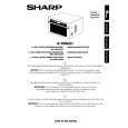
This oven is designed with a hot air heating system where food is not directly heated by the heating element, but is heated by forced circulation of the hot air produced by the heating elements. The air heated by the heating elements is circulated through the convection passage provided on the outer casing of the oven cavity by means of the convection fan which is driven by the convection motor CM. It then enters the inside of the oven through the vent holes provided on the top and left sides of the oven. Next, the hot air heats the food on the turntable and leaves the oven cavity through the vent in the center of the oven cavity back side wall. Without leaving the oven, this hot air is reheated by the heating elements, passes through the convection passage and enters the inside of the oven cavity again, in a continuing cycle. In this way, the hot air circulates inside the oven cavity to raise its temperature and, at the same time, comes into contact with the food being cooked. When the temperature inside the oven cavity reaches the selected temperature, the heating elements are de-energized. When the temperature inside the oven cavity drops below the selected temperature, the heating elements are energized again. In this way, the inside of the oven cavity is maintained at approximately the selected temperature. When the convection time reaches 0, the heating elements are de-energized and the convection fan stops operating and the oven shuts off. Flow of hot air: The rotation direction of the convection motor CM is controlled by relay RY6. When the convection fan rotates clockwise, the hot air from the oven cavity left side wall blows stronger than one from the oven cavity top wall. ( This mode is called �Convection mode�.) When the convection fan rotates counterclockwise, the hot air from the oven cavity top wall blows stronger than one from the oven cavity left side wall. (This mode is called �JET mode�.)
Top heating element unit
SIDE HEATER THERMAL CUT-OUT TC2
The thermal cut-out located on the thermal cover left is designed to prevent damage to the side heating element unit if an over heated condition develops in the top heating element unit due to convection fan failure, thermistor failure, obstructed air ducts, dirty or blocked air intake, etc. Under normal operation, the thermal cut-out remains closed. However, when abnormally high temperature are reached within the side heating element unit, the thermal cut-out will open at 150�C causing the oven to shut down. When the thermal cut-out has cooled, the thermal cut-out closes at 130�C.
TOP HEATING ELEMENT H1
The top heating element is located at the top of the oven cavity. It is intended to heat air driven by the convection fan. The heated air is kept in the oven and force-circulated and reheated by the top heating element.
SIDE HEATING ELEMENT H2
The side heating element is located at the left side of the oven cavity. It is intended to heat air driven by the convection fan. The heated air is kept in the oven and forcecirculated and reheated by the top heating element.
TURNTABLE MOTOR TTM
The turntable motor rotates the turntable located in the bottom of the oven cavity, so that the food on the turntable is cooked evenly during cooking. The turntable may turn in either direction.
FAN MOTOR (MAGNETRON SIDE) FM
The fan motor drives a blade which draws external cool air. This cool air is directed through the air vents surrounding the magnetron and cools the magnetron. This air is channelled through the oven cavity to remove steam and vapors given off from the heating foods. It is then exhausted through the exhausting air vents at the oven cavity.
Side heating element unit
JET mode Convection mode
Convection fan
FRONT VIEW
Figure D-2. Rotation direction of convection fan
11
|
|
|
> |
|