|
|
|
Productos
|
|
Información
|
|
Destacado
|
|
|
 |
|
|
No hay comentarios de productos.
FUNCTION OF IMPORTANT COMPONENTS
MONITOR SWITCH SW3 The monitor switch is activated (the contacts opened) by the upper latch head on the door while the door is closed. The switch is intended to render the oven inoperative by means of blowing the fuse F2 F8A when the contacts of the monitored latch switch SW1 fail to open when the door is opened. Function 1. When the door is opened, the contacts (COM-NC) of monitor switch SW3 close (to the ON condition) due to their being normally closed and contacts (COM-NO) open. At this time the contacts (COM-NO) of monitored latch switch SW1 is in the OFF condition (contacts open) due to their being normally open contact switches. 2. As the door goes to a closed position, the monitor switch SW3 contacts (COM-NC) are opened and contacts (COMNO) closed and then contacts (COM-NO) of monitored latch switch SW1 and stop switch SW2 are closed.(On opening the door, each of these switches operate inversely.) 3. If the door is opened and the monitored latch switch SW1 contacts (COM-NO) fail to open, the fuse F2 (F8A) blows immediately after closing of the monitor switch (COM-NC) contacts. CAUTION: BEFORE REPLACING A BLOWN FUSE F2 F8A, TEST THE MONITORED LATCH SWITCH SW1 AND MONITOR SWITCH SW3 FOR PROPER OPERATION. (REFER TO CHAPTER �TEST PROCEDURE�).
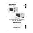
ASYMMETRIC RECTIFIER
The asymmetric rectifier is solid state device that prevents current flow is both directions. And it prevents the temperature rise of the power transformer by blowing the fuse F2 F8A when the high voltage rectifier is shorted.
D2 D1
ASYMMETRIC RECTIFIER
C HIGH VOLTAGE RECTIFIER
The rated peak reverse voltage of D1 of the asymmetric rectifier is 6 KV The rated peak reverse voltage of D2 of the asymmetric rectifier is 1.7 KV. D1 and D2 of the asymmetric rectifier or high voltage rectifier are shorted when the each peak reverse voltage goes beyond the each rated peak reverse voltage. (The process of the blowing the fuse F2 F8A.) 1. The high voltage rectifier is shorted by any causes when microwave cooking or dual cooking. 2. The peak reverse voltage of D2 of the rectifier goes beyond the rated peak reverse voltage 1.7 KV in the voltage doubler circuit. 3. D2 of the rectifier is shorted. 4. The large electric currents flow through the high voltage winding of the high voltage transformer. 5. The large electric currents beyond 8A flow through the primary winding of the high voltage transformer. 6. The fuse F2 F8A blows by the large electric currents. 7. The power supplying to the high voltage transformer is cut off.
FUSE F2 F8A 250V
1. If the wire harness or electrical components are shortcircuited, this fuse blows to prevent an electric shock or fire hazard. 2. The fuse also blows when monitored latch switch SW1 remains closed with the oven door open and when the monitor switch SW2 contact (COM-NC) closes. 3. The fuse also blows when the asymmetric rectifier, H.V. rectifier,.H.V. wire harness, H.V. capacitor, magnetron or secondary winding of high voltage transformer is shorted
NOISE FILTER
The noise filter assembly prevents radio frequency interference that might flow back in the power circuit.
TURNTABLE MOTOR TTM
The turntable motor drives the roller stay to rotate the turntable.
TC TRANSFORMER
TC transformer converts A.C. line voltage into low voltage to drive the control unit.
FAN MOTOR FM
The fan motor drives a blade which draws external cool air. This cool air is directed through the air vanes surrounding the magnetron and cools the magnetron. This air is channeled through the oven cavity to remove steam and vapours given off from the heating foods. It is then exhausted through the exhausting air vents at the oven cavity.
THERMAL CUT-OUT TC1 150�C (OVEN)
The thermal cut out protects the oven against overheat during grill cooking, convection cooking or dual (combination) cooking. If the temperature rises above 150�C because the fan motor is interrupted, the air inlet duct is blocked or the ventilation openings are obstructed, the thermal cut-out opens and switches off the all electrical parts. When the oven cools itself down to the operating temperature of 130�C, the contacts of the thermal cut-out will close again.
CONVECTION MOTOR CM
The convection motor drives the convection fan and provide the heated air.
THERMAL CUT-OUT TC2 125�C (MG)
This thermal cut-out protects the magnetron against overheat. If the temperature goes up higher than 125�C because the fan motor is interrupted or the ventilation openings are blocked, the thermal cut-out TC2 will open and line voltage to the high voltage transformer T will cut off and operation of the magnetron MG will be stopped. The defective thermal cut-out must be replaced with a new one. R-84ST - 12
TOP GRILL HEATING ELEMENT GH
The grill heating element is provided to brown the food and is located on the top of the oven cavity.
BOTTOM GRILL HEATING ELEMENT BH
The grill heating element is provided to brown the food and is located at the base of the oven cavity.
|
|
|
> |
|