|
|
|
Productos
|
|
Información
|
|
Destacado
|
|
|
 |
|
|
No hay comentarios de productos.
R-21AT
FAN MOTOR REPLACEMENT
REMOVAL
1. CARRY OUT 3D CHECKS. 2. Remove the one (1) screw holding the noise filter to the chassis support. 3. Release the noise filter from the tab on the fan duct. 4. Disconnect the wire leads from the fan motor. 5. Remove the one (1) screw holding the capacitor holder to the oven cavity rear plate. 6. Remove the one (1) screw holding the fan duct to the oven cavity rear plate. 7. Remove the fan duct from the oven. 8. Remove the fan blade from the fan motor shaft according to the following procedure. 9. Hold the edge of the rotor of the fan motor by using a pair of groove joint pliers. CAUTION: * Make sure that no metal pieces enter the gap between the rotor and the stator of the fan motor because the rotor is easily shaven by pliers and metal pieces may be produced. * Do not touch the pliers to the coil of the fan motor because the coil may be cut or injured. * Do not disfigure the bracket by touching with the pliers. 10.Remove the fan blade from the shaft of the fan motor by pulling and rotating the fan blade with your hand. 11. Now, the fan blade will be free.
Coil Groove joint pliers
CAUTION: * Do not reuse the removed fan blade because the hole (for shaft) may be larger than normal. 12.Remove the two (2) screws holding the fan motor to the fan duct. 13.Now, the fan motor is free. INSTALLATION 1. Install the fan motor to the fan duct with the two (2) screws. 2. Install the fan blade to the fan motor shaft according to the following procedure. 3. Hold the center of the bracket which supports the shaft of the fan motor on the flat table. 4. Install the fan blade to the shaft of fan motor by pushing the fan blade with a small, light weight, ball peen hammer or rubber mallet. CAUTION: * Do not hit the fan blade hard when installing because the bracket may be disfigured. * Make sure that the fan blade rotates smooth after installation. * Make sure that the axis of the shaft is not slanted. 5. Install the fan duct to the oven cavity rear plate with the one (1) screw. 6. Install the capacitor holder to the oven cavity rear plate with the one (1) screw. 7. Install the noise filter to the fan duct and the chassis support with the one (1) screw. 8. Re-connect the wire leads to the fan motor.
Shaft
Stator Gap Bracket Rotor
Shaft Axis Stator Rotor
These are the positions that should be pinched with pliers Table
Center of bracket
Rear view
Side view
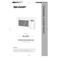
POWER SUPPLY CORD REPLACEMENT
Removal
1. CARRY OUT 3D CHECKS. 2. Remove the one (1) screw holding the green/yellow wire to the cavity rear plate. 3. Disconnect the leads of the power supply cord from the noise filter, referring to the Figure C-3(a). 4. Release the power supply cord from the oven cavity rear plate. 5. Now, the power supply cord is free.
Oven Cavity Back Plate Screw Green/Yelow Wire Brown Wire
L RED WHT
Re-install
1. Insert the moulding cord stopper of power supply cord into the square hole of the oven cavity rear plate, referring to the Figure C-3(b). 2. Install the earth wire lead of power supply cord to the cavity rear plate with one (1) screw and tight the screw. 3. Connect the brown and blue wire leads of power supply cord to the noise filter correctly, referring to the Pictorial Diagram.
Moulding Cord Stopper Power Supply Cord Oven Cavity Rear Plate Square Hole
Power Supply Cord
Chassis Support
Bule Wire Noise Filter
N
Figure C-3 (a) Replacement of Power Supply Cord
22
Figure C-3(b). Power Supply Cord Replacement
|
|
|
> |
|